Сварочное оборудование Awelco MIG ONE - инструкция пользователя по применению, эксплуатации и установке на русском языке. Мы надеемся, она поможет вам решить возникшие у вас вопросы при эксплуатации техники.
Если остались вопросы, задайте их в комментариях после инструкции.
"Загружаем инструкцию", означает, что нужно подождать пока файл загрузится и можно будет его читать онлайн. Некоторые инструкции очень большие и время их появления зависит от вашей скорости интернета.
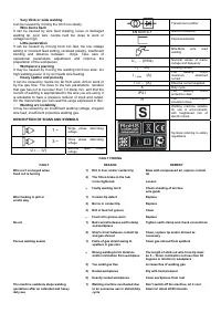

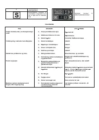


La macchina cessa improvvisamente
di funzionare dopo un uso prolungato
5) Pezzi con molta ruggine
1) La macchina si è surriscaldata
per un uso eccessivo e la
protezione
termica è intervenuta
altro mezzo
Pulire i pezzi dalla ruggine
Lasciare raffreddare la macchina per
almeno 20 – 30 minuti
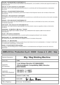
ENGLISH
GENERAL DESCRIPTION
MIG welders which can weld flux cored gasless wire.
WHEN WELDING, USE PROMIG JET WELDING SPRAY
TO OBTAIN OPTIMAL WELDING. THE USE OF THIS
PRODUCT WILL ENHANCE THE BINDING OF THE WELD
AND REDUCE SPATTERING.
1. INSTALLATION
1.1. ELECTRICAL CONNECTION
The welding machine is fitted with a suitable primary cable
which we strongly recommend you to do not extend: if it is
necessary to extend it, use a cable having the same section
of the primary cable.
Before connecting the machine to the outlet, check that your
supply voltage is like the machine’s voltage and that the
furneshed power is sufficient to feed the full load machine.
Make sure that the electric plant is provided with a sufficient
earth connection.
Supply voltage
The supply voltage is of 230V.
1.2. EARTH CONNECTION
A suitable earth cable connected to a clamp is supplied with
the welding machine. The earth clamp should be attached to
the workpiece itself. The must be very good connection
wherever made, as a poor or dirty connection will produce
difficult welding conditions and could result in a bad weld.
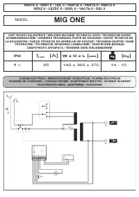
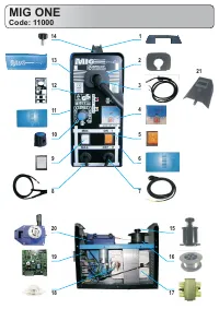
2. TECHNICAL INFORMATION
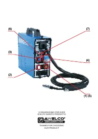
The welding machine has an On-Off switch (1), with
luminous led that indicates the operation of the car (7).
The welder has a switch (2) that provides 2-position power,
to select based on the power of which need is had.
Using the knob (3) placed on the frontal you can regulate the
welding wire speed. The knob should be used in conjunction
with the voltage switch to give a smooth and perfect arc.
You can see the speed of the wire through an indicator in
M/min (4) on the front panel of the machine.
The machine is fitted with a thermal overload protection
which will automatically interrupt the welding current on
reaching excessive temperatures; in which instance a yellow
pilot light (5) will switch on. Once the temperature has
decreased to a level low enough to allow welding, the light
will switch itself off and the machine is again ready for use.
The wire speed control electronic card is protected against
peak of voltage by means of an easy to repalce fuse located
on the wire setting card. Should said fuse burn, the machine
will stop automatically and the malfunction will be signalled
by a led located on the machine’s front panel (6). In order to
change the burnt fuse, disconnect the machine from tha
mains, unscrew the right side panel and replace the fuse by
pulling it out. Use a small screwdriver to lever the fuse out. In
any case do not connect the welding machine to the power
generator.
3. WELDING MODE
3.1. NO-GAS
The machine was designed for NO-GAS welding.
4. SPOOL WIRE AND TORCH INSTALLATION
4.1. SPOOLS INSTALLATION
You can use spools of Kg. 0,2 , Kg. 0,4.
4.2. WIRE-FEEDER MOTOR
Make sure that the size of the groove in the feed roll
corresponds to the welding wire size being used. The
machines are arranged with feed roll for Ø 0,6 and 0,8 wire.
Used for wire Ø 0.9, you can use the supplied roll. The feed
roll has the wire diameter stamped on its side. The machines
are equipped with proper shagreneed rolls suitable for
welding with flux cored wire without gas protection. In any
case, the machine uses only wire type FLUX.
4.3. FEEDING WIRE INTO THE WELDING TORCH
Cut the first 10 cm of wire and then check that there are no
burrs or distortions at the cut end. Release the small wheel
which is connected to the pressure arm by unscrewing the
pressure screw and pass the wire through the feed roll’s
groove and then re-insert the wire into the guide. At this
point, make sure that the wire lies in the feed roll’s groove in
a natural line. Drop the pressure arm on the wire and swing it
back under the pressure screw. Pressure on the welding wire
is regulated by turning the pressure screw, the correct
pressure being critically important to the smooth operation of
the welding machine. The optimum pressure is the one
which ensures that the wire runs smoothly though allows the
feed roll to slip in the event of a blockage in the torch. It is
possible to adjust the friction of the paddle hub. If the hub
over-runs, then increase the friction pressure in order to
always have the spool wire drawn. On the contrary, if the
friction pressure is too much, some tension can be released
to obtain a regular wire feeding.
4.4. TORCH CONNECTION
The torch is connected directly to the welding machine so it
is ready for use. A probable replacement of the torch must
be done with care and if possible by a technician. To replace
contact tips, it is necessary to unscrew or to pull it. Replace
tip, check that it corresponds with the wire size and replace
the gas shroud. For good wire feeding during welding
operations, it is essential that the correct size parts are used
for each wire. Keep always clean the contact tip.
5. WELDING GUIDE
5.1. GENERAL RULE
When welding on the lowest output settings, it is necessary
to keep the arc as short as possible. This should be achieved
by holding welding torch as close as possible and at an
angle of approximately 60 degrees to the workpiece. The arc
length can be increased when welding on the highest
settings, an arc length up to 20 mm can be enough when
welding on maximum settings.
5.2. GENERAL WELDING TIPS
From time to time, some faults may be observed in the weld
owing to external influences rather due to welding machine’s
faults. Here are some that you may come across :
· Porosity
Small holes in the weld, caused by break-down in gas
coverage of the weld or sometimes by foreign bodies
inclusion. Remedy is, usually, to grind out the weld.
Remember, check before the gas flux (about 8
liters/minutes), clean well the working place and finally
incline the torch while welding.
· Spatter
Small balls of molten metal which come out of the arc. A little
quantity is unavoidable, but it should be kept down to a
minimum by selecting correct settings and having a correct
gas flow and by keeping the welding torch clean.
·
Narrow heap welding
Can be caused by moving the torch too fast or by an
incorrect gas flow.

