Культиваторы AL-KO MH 7505 V2R - инструкция пользователя по применению, эксплуатации и установке на русском языке. Мы надеемся, она поможет вам решить возникшие у вас вопросы при эксплуатации техники.
Если остались вопросы, задайте их в комментариях после инструкции.
"Загружаем инструкцию", означает, что нужно подождать пока файл загрузится и можно будет его читать онлайн. Некоторые инструкции очень большие и время их появления зависит от вашей скорости интернета.


en
Installation
22
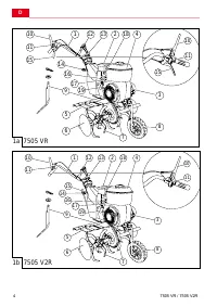
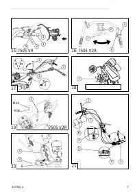
7505 VR / 7505 V2R
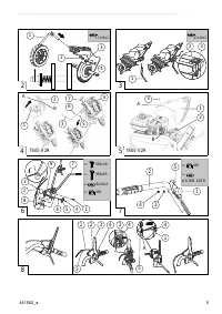
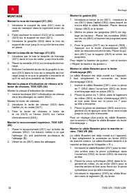
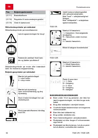
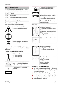
Assembling the gear lever:
2. Insert the gear lever (04/3) into the eye (A) on
the frame (04/7).
3. Attach the gear lever on the gear shaft (04/4)
using the screw (04/5) and the nut (04/6).
Mounting the upper housing cover, 7505 V2R
(05)
1. Place the housing cover (05/1) on the trans-
mission (05/2). Ensure that the hole (A) is
above the hole (B).
2. Screw the screw (05/3) into the holes.
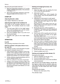
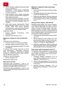
Mounting the handlebar (06)
1. Inserting and tightening the screw (06/1): In-
sert the screw (06/1) through the eye (06/2)
in which the Bowden cable is already located.
Put on the nut (06/3) and tighten.
2. Attaching grips (06/5) for the height adjust-
ment: Place the washers (06/6) on the screws
(06/4) and lightly screw in the grips.
3. Fixing the handlebar (06/7) to the holder
(06/8): Press the cam lever (06/9) down.
Place the handlebar (06/7) on the holder
(06/8) and screw the grips tight.
To adjust the height of the handlebar, see section
“Setting the height of the handlebar".
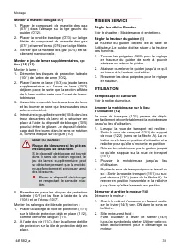
Mount the Bowden cable for the clutch lever
(08)
The Bowden cable is already mounted on the ap-
pliance; it only needs to be connected to the clutch
lever (08/3).
1. Insert the Bowden cable (08/1) with the T-ter-
minal (08/4) into the opening (08/2) of the pre-
mounted clutch lever (08/3).
2. Insert the T-terminal (08/4) into the middle
support (08/3) of the clutch lever (08/3) and
pull the T-terminal firmly until it locks in place.
3. Insert the plastic terminal (08/5) into the sup-
port (A) and firmly press it down until it locks
in place.
For fine adjustment of the Bowden cable, see sec-
tion “Readjusting the Bowden cable of the clutch
lever".
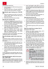
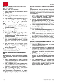
Mounting the Bowden cable for the reverse
gear, 7505 VR (09)
The Bowden cable is already mounted on the ap-
pliance; it only needs to be connected to the lever
(09/3) for the reverse gear. The Bowden cable for
the reverse gear is marked with the label “R”.
1. Insert the Bowden cable (09/1) for the re-
verse gear with the cylindrical terminal into the
opening (09/2) of the lever (09/3) for the re-
verse gear.
2. Insert the cylindrical terminal (09/4) into the
middle support (A) of the lever (09/3) for the
reverse gear and pull on the cylindrical termi-
nal firmly until it locks in place.
3. Insert the controller (09/5) of the Bowden ca-
ble into the support (B) of the lever.
Mounting the gas lever (07)
1. Insert the gas lever assembly (07/1) into the
hole on the left bar of the handlebar (07/2).
2. Place the spring washer (07/3) onto the thre-
aded pin of the gas lever assembly (07/1) and
screw the nut (07/4) firmly onto the threaded
pin.
3. Check that the gas lever (07/5) can move fre-
ely.
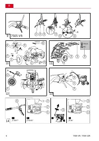
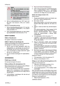
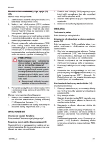
Mount the wide tiller set, option (10) (11)
Mounting the tiller blades:
1. Remove the lateral protective discs (10/1)
from the tiller blade shaft (10/2).
2. Place the tiller blade shaft (10/3) of the wide
tiller set onto the already mounted tiller blade
shaft (10/2) in such way that the edge of the
tiller blades points towards the front side of
the cultivator.
3. Push both tiller blade shafts into each other,
turning both tiller blade shafts in such a way
that the holes of the two shafts coincide.
4. Push the split safety pin (10/4) through the ho-
les of the tiller blade shafts and secure against
sliding out again with the safety locking me-
chanism (10/5). The safety locking mecha-
nism must be rotated in rotation direction A,
exactly as displayed in the figure (10).
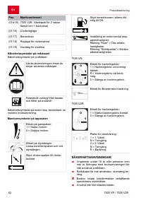
CAUTION!
Risk of injury due to detaching
machine parts!
If the safety locking mechanism ro-
tates counter to the direction of ro-
tation, the wide tiller set can detach
if the cultivator is running and injure
people.
Insert the safety locking mecha-
nism in the direction of rotation.
5. Replace the lateral protective discs (10/1) and
attach them with the screw (10/6) and the nut
(10/7).
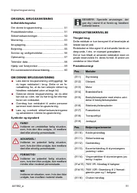
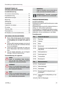
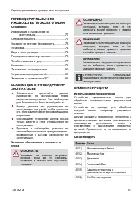
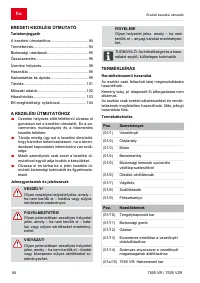
Содержание
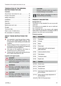
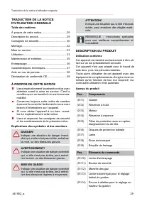
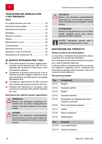
- 71 ПЕРЕВОД ОРИГИНАЛЬНОГО; ОПИСАНИЕ ПРОДУКТА
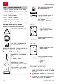
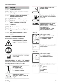
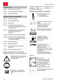
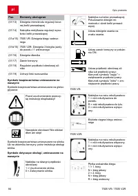
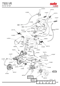
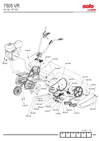
- 72 Позиция Узлы
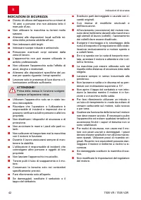
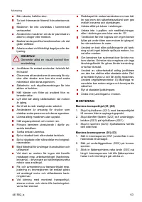
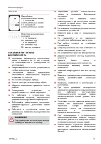
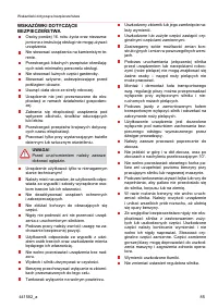
- 73 УКАЗАНИЯ ПО ТЕХНИКЕ
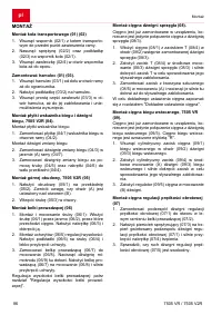
- 74 УСТАНОВКА; Установите транспортировочное колесо
- 75 Установите боуденовский трос задней
- 76 ВВОД В ЭКСПЛУАТАЦИЮ; Регулировка боуденовских тросов; ПОСЛЕДОВАТЕЛЬНОСТЬ; Заполнение топливом
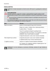
- 77 Использование тормозной шпоры; ТЕХОБСЛУЖИВАНИЕ И УХОД; во время проведения работ по
- 78 среды отходами отработанного
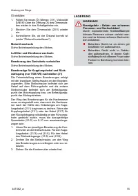
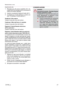
- 79 ХРАНЕНИЕ
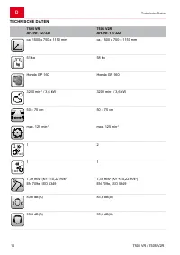
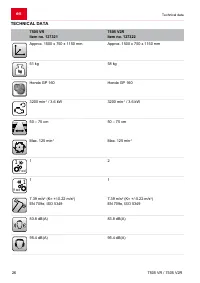
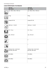
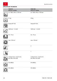
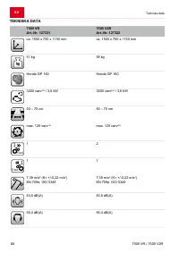
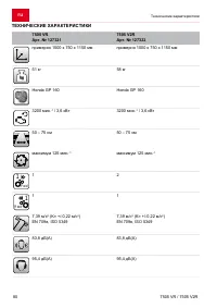
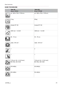
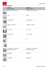
- 80 ТЕХНИЧЕСКИЕ ХАРАКТЕРИСТИКИ
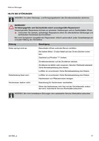
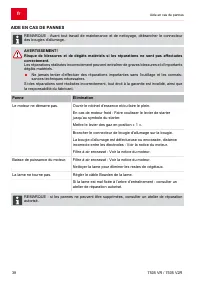
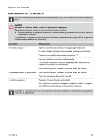
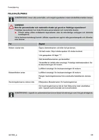
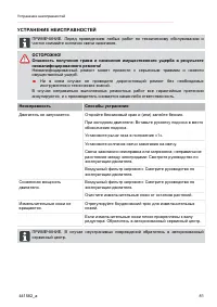
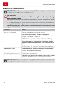
- 81 УСТРАНЕНИЕ НЕИСПРАВНОСТЕЙ
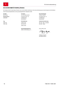
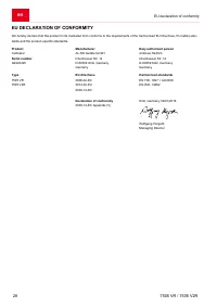
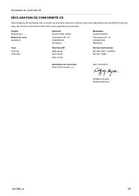
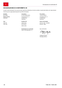
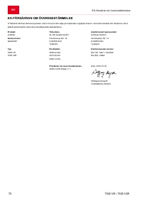
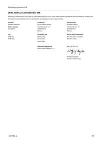
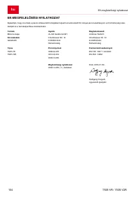
- 82 ЗАЯВЛЕНИЕ О СООТВЕТСТВИИ ЕС


