
Компрессоры COMPRAG F-0708 11410201 - инструкция пользователя по применению, эксплуатации и установке на русском языке. Мы надеемся, она поможет вам решить возникшие у вас вопросы при эксплуатации техники.
Если остались вопросы, задайте их в комментариях после инструкции.
"Загружаем инструкцию", означает, что нужно подождать пока файл загрузится и можно будет его читать онлайн. Некоторые инструкции очень большие и время их появления зависит от вашей скорости интернета.


20
Version 1.3
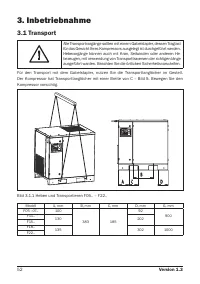
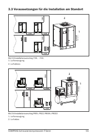
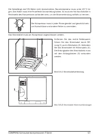
Ensure that the floor of the facility can withstand the weight of the compressor. Install the
compressor on a level surface that is able to bear its weight. Adjust the horizontal axis of the
compressor using a levelling instrument. If the compressor is not anchored to the base on
which it is installed, the tilt angle with respect to the horizontal surface must not exceed 3°.
If the compressor is anchored to the base on which it is installed, the tilt angle with respect
to the horizontal surface must not exceed 7°. Install the compressor in a facility where pre
-
cipitation cannot reach. Choose a facility for installing the compressor with a minimum level
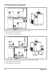
of dust. Install the compressor at least 1.5 m from walls.
If multiple compressors are installed, there should be a 1.5 m minimum distance between
each compressor. There should be a 4 m safety distance from the area of the operated equip
-
ment connected to the compressor. The facility in which the compressor is installed must be
fitted with a combined extract-and-input ventilation system.
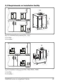
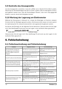
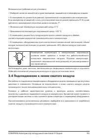
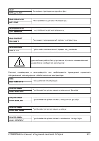
The facility where the compressor is installed should be provided
with air inflow equivalent to twice the compressor’s capacity.
The volume of extraction ventilation must not exceed 40% of the air inflow capacity of the
input ventilation in a facility where the compressor is installed and fitted with an extract-and-
input ventilation system. The compressor should not be installed in a facility where the tempera-
ture may drop below +5°С. In order to extract hot air flowing out the compressor, an air duct
may be used that is up to 3 m in length and with a cross section 20% larger than that of the
air-outflow orifice from the compressor’s radiator. If an air duct longer than 3 m is used, ad
-
ditional duct fans should be used.
3.4 Connection to the compressed airline
Provide the throughput capacity of the compressed-air line in accordance with the perfor-
mance of the compressor. In order to avoid damage associated with seal failure of the com-
pressed-air line, the compressor should be connected via a flexible hose. All components
of the compressed-air line must have a working pressure no less than the compressor’s
nominal pressure. Use a pressure vessel with a capacity corresponding to the compressor’s
performance and the compressed air consumer.
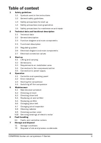
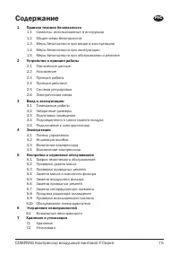
Содержание
- 75 COMPRAG Компрессор воздушный винтовой F-Серия; Содержание
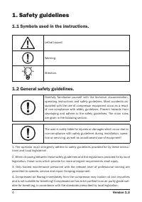
- 76 Правила техники безопасности; Общие правила безопасности
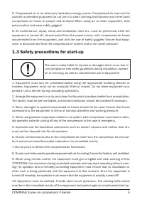
- 77 Меры безопасности при вводе в эксплуатацию
- 78 Меры безопасности при эксплуатации
- 79 Меры безопасности при обслуживании и ремонте
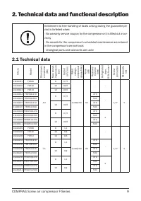
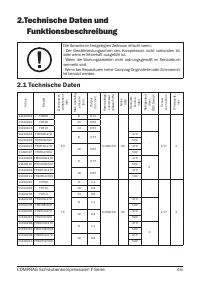
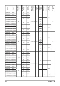
- 81 Технические данные
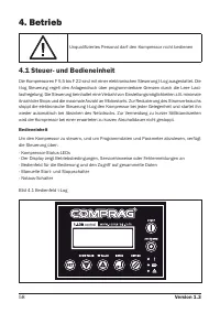
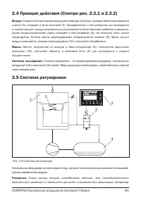
- 85 Система регулировки
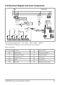
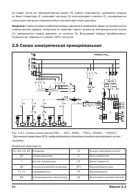
- 86 Схема электрическая принципиальная
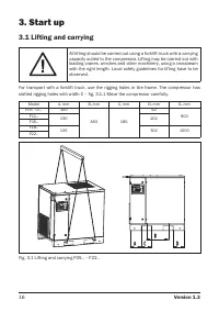
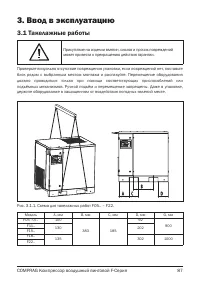
- 87 Ввод в эксплуатацию; Такелажные работы
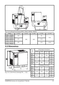
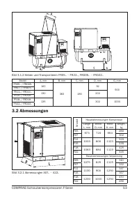
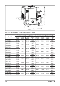
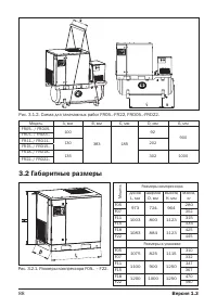
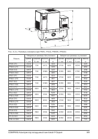
- 88 Габаритные размеры
- 90 Подготовка помещения
- 91 Подсоединение к линии сжатого воздуха
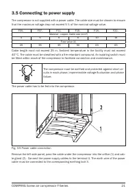
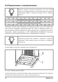
- 92 Подключение к электропитанию
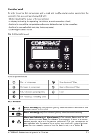
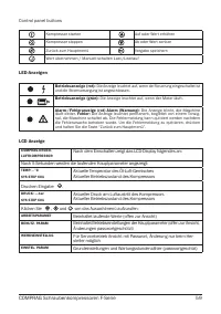
- 93 Панель управления
- 102 Выключение компрессора
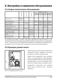
- 103 Настройка и сервисное обслуживание; График технического обслуживания
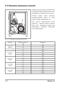
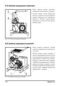
- 104 Проверка приводных ремней
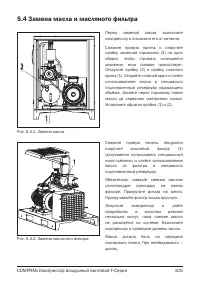
- 105 Замена масла и масляного фильтра
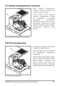
- 107 Замена сепарационного элемента
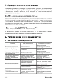
- 108 Устранение неисправностей; Возможные неисправности
- 109 Хранение и утилизация


