
Компрессоры COMPRAG F-0708 11410201 - инструкция пользователя по применению, эксплуатации и установке на русском языке. Мы надеемся, она поможет вам решить возникшие у вас вопросы при эксплуатации техники.
Если остались вопросы, задайте их в комментариях после инструкции.
"Загружаем инструкцию", означает, что нужно подождать пока файл загрузится и можно будет его читать онлайн. Некоторые инструкции очень большие и время их появления зависит от вашей скорости интернета.


13
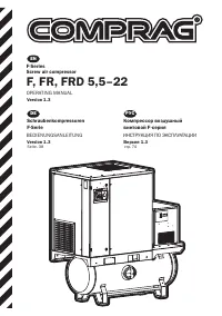
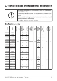
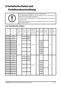
COMPRAG Screw air compressor F-Series
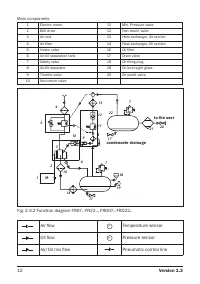
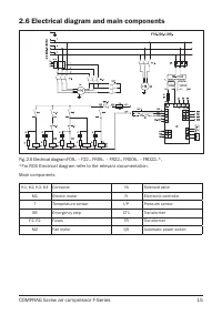
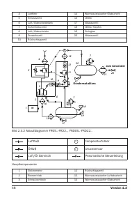
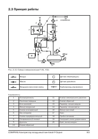
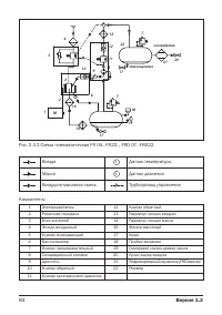
Main components
1
Electric motor
12
Non-return valve
2
Belt drive
13
Heat-exchanger, Air section
3
Air end
14
Heat-exchanger, Oil section
4
Air filter
16
Oil filter
5
Intake valve
17
Drain valve
6
Air-Oil separation tank
18
Oil filling plug
7
Safety valve
19
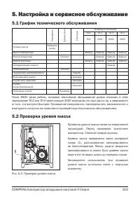
Oil level sight glass
8
Air-Oil separator
20
Air outlet valve
9
Throttle valve
21
Refrigerated dryer (ARD only)
10
Non-return valve
22
Pressure vessel
11
Min. Pressure valve
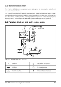
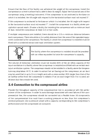
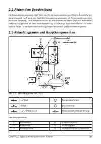
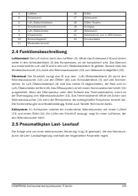
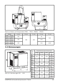
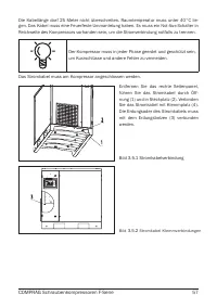
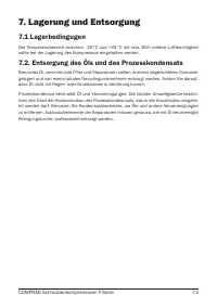
2.4 Functional description (see Fig. 2.1 and Fig. 2.2)
Air flow:
Air drawn through Air filter (4) and open Intake valve (5) into compressor Air-end (3) is compressed.
Compressed air and oil flow into Air-Oil separation tank (6). The air is discharged via Min.
Pressure valve (11) through Heat-exchanger (13) towards the Air Outlet Valve (20).
Oil flow:
Air pressure forces oil from the air-oil separation tank (6) through the heat-exchang-
er (14) and the oil filter (16) to the compressor air-end (3) and the lubrication points. In the
air-oil separation tank (6), most of the oil is removed centrifugally; the rest is removed by
the air-oil separator (8). The oil system is fitted with a thermostatic valve (15). When the oil
temperature is below the set-point of the thermostatic valve, the thermostatic valve shuts
off the oil supply from oil heat-exchanger (14). The thermostatic valve starts opening the
supply from heat-exchanger (14) when the oil temperature exceeds the valve’s setting. The
setting of the thermostatic valve depends on the model. See table Technical Data.
Cooling system:
The cooling system comprises a combined air section (13) and an oil sec-
tion (14) heatexchanger. A cooling fan, mounted in the fresh air intake section, generates
the cooling air in order to cool the heat-exchanger.
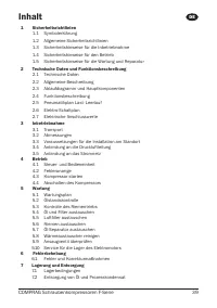
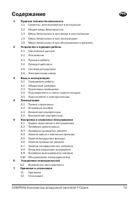
Содержание
- 75 COMPRAG Компрессор воздушный винтовой F-Серия; Содержание
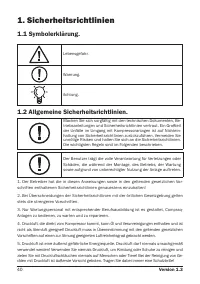
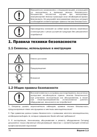
- 76 Правила техники безопасности; Общие правила безопасности
- 77 Меры безопасности при вводе в эксплуатацию
- 78 Меры безопасности при эксплуатации
- 79 Меры безопасности при обслуживании и ремонте
- 81 Технические данные
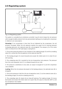
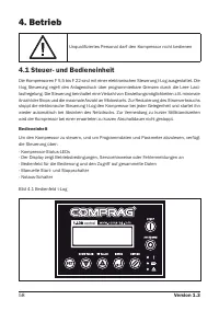
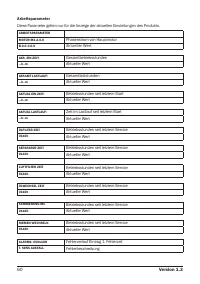
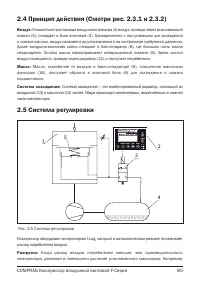
- 85 Система регулировки
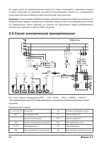
- 86 Схема электрическая принципиальная
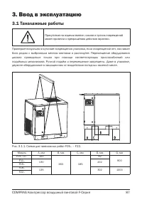
- 87 Ввод в эксплуатацию; Такелажные работы
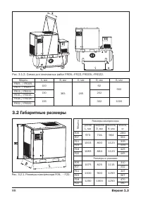
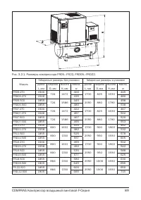
- 88 Габаритные размеры
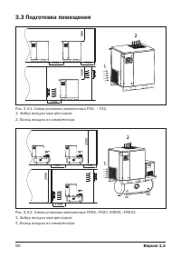
- 90 Подготовка помещения
- 91 Подсоединение к линии сжатого воздуха
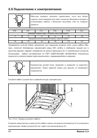
- 92 Подключение к электропитанию
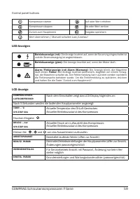
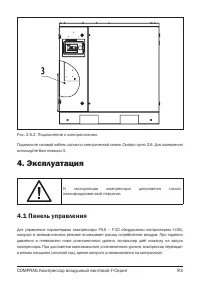
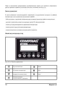
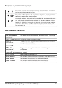
- 93 Панель управления
- 102 Выключение компрессора
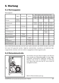
- 103 Настройка и сервисное обслуживание; График технического обслуживания
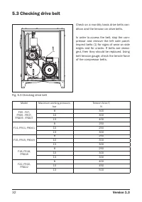
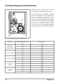
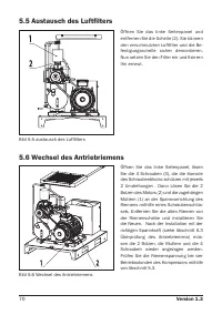
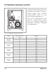
- 104 Проверка приводных ремней
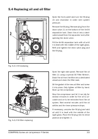
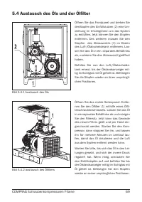
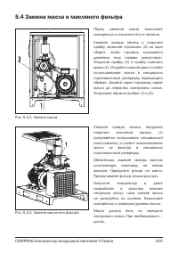
- 105 Замена масла и масляного фильтра
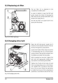
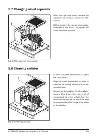
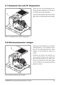
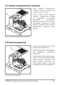
- 107 Замена сепарационного элемента
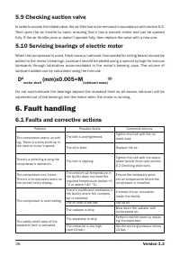
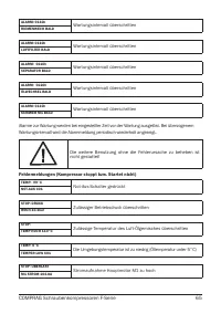
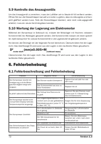
- 108 Устранение неисправностей; Возможные неисправности
- 109 Хранение и утилизация


