
Газонокосилки STIGA TWINCLIP 950 SQ AE 294513898/ST1 - инструкция пользователя по применению, эксплуатации и установке на русском языке. Мы надеемся, она поможет вам решить возникшие у вас вопросы при эксплуатации техники.
Если остались вопросы, задайте их в комментариях после инструкции.
"Загружаем инструкцию", означает, что нужно подождать пока файл загрузится и можно будет его читать онлайн. Некоторые инструкции очень большие и время их появления зависит от вашей скорости интернета.


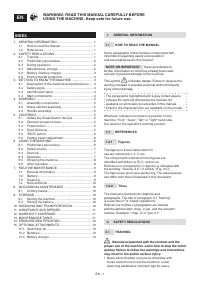


EN - 5
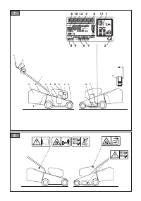
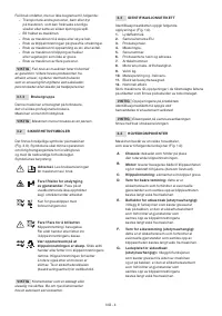
K.
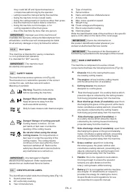
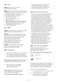
Operator presence lever:
this lever enables
the cutting means and drive to be operated. The
motor stops when both levers are released.
L.
Drive engagement lever:
this lever
engages the drive to the wheels and
allows the machine to move forward.
M.
Hatch for accessing the battery compartment
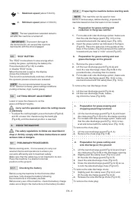
N.
Safety key (Deactivation device):
The key
enables / disables the machine electric circuit.
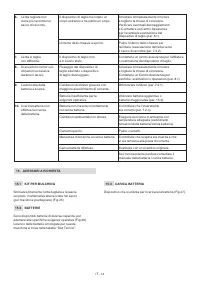
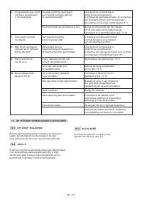
O.
Battery charger
(if it is not supplied with the
machine, see chapter 15 “attachments on
request”): device used to recharge the battery.
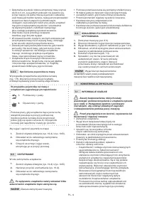
4. ASSEMBLY
The safety regulations to follow are described in
chap. 2. Strictly comply with these instructions to avoid
serious risks or dangers.
For storage and transport purposes, some components of
the machine are not installed in the factory and have to be
assembled after unpacking. Follow the instructions below.
Unpacking and completing the assembly should
be done on a flat and stable surface, with enough
space for moving the machine and its packaging,
always making use of suitable equipment. Do not use
the machine until all the instructions provided in the
“ASSEMBLY” section have been carried out.
4.1 ASSEMBLY COMPONENTS
The packaging includes assembly components.
4.1.1 Unpacking
1.
Carefully open the packaging, paying
attention not to lose components.
2.
Consult the documentation in the box,
including these instructions.
3.
Remove all the unassembled parts from the box.
4.
Dispose of the box and packaging in
compliance with local regulations.
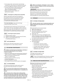
Before assembling, make sure the safety key is
not inserted into its housing.
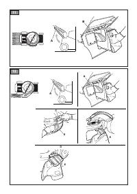
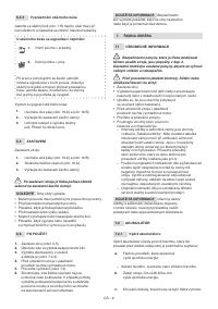
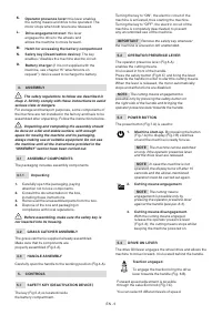
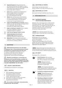
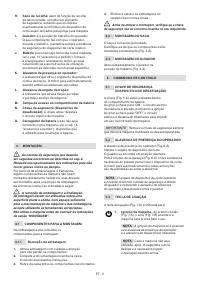
4.2 GRASS CATCHER ASSEMBLY
The grass catcher is supplied already assembled.
Make sure that its components are
properly assembled (Fig.3.A).
4.3 HANDLE ASSEMBLY
Carefully open the handle to the working position (Fig.4.A).
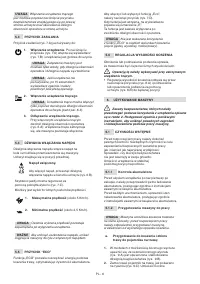
5. CONTROLS
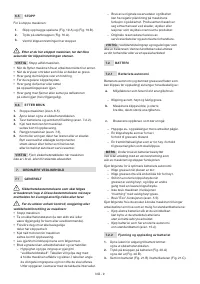
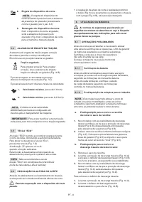
5.1
SAFETY KEY (DEACTIVATION DEVICE)
The key (Fig.5.A) is located inside
the battery compartment.
Turning the key to "ON", the electric circuit of the
machine is activated, thus starting the machine.
Turning the key to "OFF", the electric circuit of the
machine is completely deactivated, to prevent
any uncontrolled use of the machine.
IMPORTANT
Remove the safety key whenever
the machine is unused or left unattended.
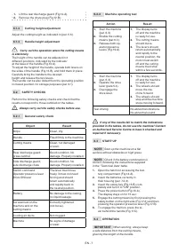
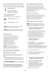
5.2 OPERATOR PRESENCE LEVER
The operator presence lever (Fig.6.A)
enables the cutting means.
It is located in front of the handle.
Press the safety button (Fig.6.C) and bring the lever
towards the handle in order to start the cutting means.
When the lever is released, the motor automatically
stops and all functions are disabled.
NOTE
The cutting means engagement is
possible only by pressing the safety button on
the right side of the handle and bringing the
operator presence lever towards the handle.
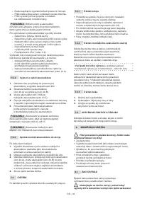
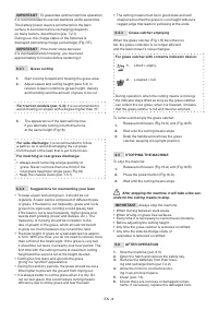
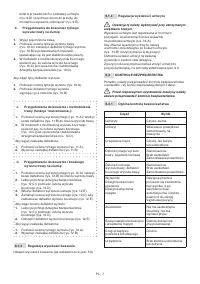
5.3 POWER BUTTON
The power button (Fig.7.A) is used to:
1. Machine start-up.
By pressing the button
(Fig.7.A) the display (Fig.7.B) switches
on and the machine is ready for use.
NOTE
The machine can be switched
on only if the operator presence lever
and the drive lever are released.
NOTE
In case the machine is not
operated, the display turns off after 15
seconds and the above-mentioned
operation must be carried out again.
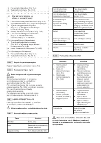
2. Cutting means engagement.
NOTE
The cutting means
engagement is possible only by
pressing the operator presence lever
against the handle (see par. 6.3).
3. Cutting means disengagement.
With the cutting means engaged,
release the operator presence lever
(Fig.6.A); the cutting means stops whilst
keeping the machine powered on.
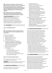
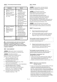
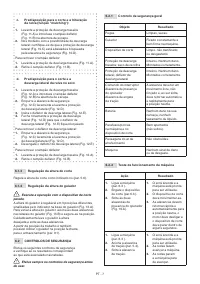
5.4 DRIVE ON LEVER
The drive ON lever engages the wheel drive and allows the
machine to move forward. It is located behind the handle.
Traction engaged.
To engage the traction bring the drive
lever towards the handle (Fig. 6.B).
Forward speed adjustment is possible
through the selection knob (Fig.7.C).
You can select 6 different levels of speed.


