
Фрезеры Bosch 0.601.613.608 - инструкция пользователя по применению, эксплуатации и установке на русском языке. Мы надеемся, она поможет вам решить возникшие у вас вопросы при эксплуатации техники.
Если остались вопросы, задайте их в комментариях после инструкции.
"Загружаем инструкцию", означает, что нужно подождать пока файл загрузится и можно будет его читать онлайн. Некоторые инструкции очень большие и время их появления зависит от вашей скорости интернета.


English |
19
Bosch Power Tools
1 619 929 J79 | (23.11.11)
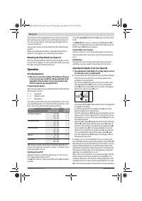
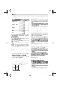
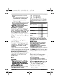
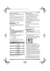
setting range of 2.0 mm; a graduation mark on the top edge of
the scale
19
corresponds with a 0.1 mm change of the setting
range. The maximum setting range is
±
8 mm.
Example:
The desired depth-of-cut is to be 10.0 mm; the trial
cut resulted in a cutting depth of 9.6 mm.
– Lift up the router and place e. g. a piece of scrap wood un-
der the guide plate
9
so that the router bit
7
cannot touch
the workpiece when lowering it. Push the release lever
22
down and slowly lower the plunge router until the depth
stop
15
faces on the step buffer
10
.
– Turn the scale
19
to “0” and loosen wing bolt
14
.
– Turn the adjustment knob
20
by 0.4 mm/4 graduation
marks (difference from set to actual value) in clockwise di-
rection and tighten the wing bolt
14
.
– Check the selected depth-of-cut by carrying out another
trial cut.
After adjusting the depth-of-cut, do not change the position of
the slide
16
on the depth stop
15
any more, so that the actual
cutting depth can be read on the scale
18
.
Working Advice
f
Protect router bits against shock and impact.
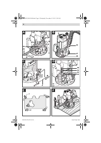
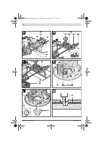
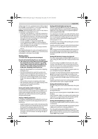
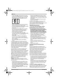
Direction of Feed and Routing Process (see figure E)
f
The routing process must always be carried out against
the rotation direction of the router bit 7 (up-cutting
motion). When routing in the direction with the rota-
tion of the router (down-cutting), the machine can
break loose, eliminating control by the user.
– Adjust the required depth-of-cut; see Section “Adjusting
the Depth-of-cut”.
– Place the machine with the router bit mounted on the
workpiece to be machined and switch the power tool on.
– Push the release lever
22
down and slowly lower the
plunge router until the adjusted depth-of-cut is reached.
Let go of the release lever
22
again to lock this cutting
depth.
– Carry out the routing process applying uniform feed.
– After finishing the cutting process, guide the plunge router
upward again to the uppermost position.
– Switch the power tool off.
Routing with Auxiliary Guide (see figure F)
For working large workpieces, e. g. when routing grooves, a
board or wood strip can be fastened to the workpiece as an
auxiliary guide alongside which the router can be guided.
Guide the router with the flattened side of the guide plate
along the auxiliary guide.
Shaping or Molding Applications
For shaping or molding applications without the use of a par-
allel guide, the router bit must be equipped with a pilot or a
ball bearing.
– Guide the switched on power tool from the side toward the
workpiece until the pilot or the ball bearing of the router bit
faces against the workpiece edge to be machined.
– Guide the power tool alongside the workpiece edge with
both hands, paying attention that the router is positioned
rectangular. Too much pressure can damage the edge of
the workpiece.
Routing with Parallel Guide (see figure G)
Slide the parallel guide
29
with the guide rods
30
into the
base plate
12
and tighten as required with the wing bolts
5
.
Additionally, the parallel guide can be adjusted lengthwise
with the wing bolts
31
and
32
.
Fine adjustment of the length is possible with the fine-adjust-
ment knob
33
after loosening both wing bolts
31
. One revolu-
tion corresponds with a setting range of 2.0 mm. One gradu-
ation mark on the fine-adjustment knob
33
changes the
setting range by 0.1 mm.
The effective contact surface of the parallel guide can be ad-
justed with the edge guide
34
.
Guide the switched on power tool with uniform feed and later-
al pressure on the parallel guide alongside the workpiece
edge.
When routing with the parallel guide
29
, the dust/chip extrac-
tion should take place via the special extraction adapter for
the parallel guide
35
. The extraction adapter
27
can remain
mounted.
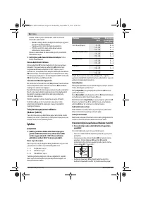
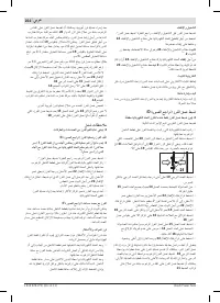
Routing with the Router Compass (see figure H)
The router compass/guide-rail adapter
36
can be used for cir-
cular routing jobs. Mount the router compass as shown in the
figure.
Screw the centring screw
41
into the thread on the router
compass. Insert the point of the centring screw into the cen-
tre of the circular arc to be routed, paying attention that point
of the screw engages into the workpiece surface.
Coarsely adjust the required radius by moving the router com-
pass and tighten the wing bolts
38
and
39
.
The length can be fine adjusted with the fine-adjustment knob
40
after loosening the wing bolt
39
. One revolution corre-
sponds with a setting range of 2.0 mm. One graduation mark
on the fine-adjustment knob
40
changes the setting range by
0.1 mm.
Guide the switched on power tool over the workpiece with the
right handle
1
and the router compass handle
37
.
Routing with Guide Rail (see figure I)
Straight routing cuts can be carried out with help of the guide
rail
43
.
The base spacer
42
must be mounted in order to compensate
the height difference.
Mount the router compass/guide-rail adapter
36
as shown in
the figure.
Fasten the guide rail
43
to the workpiece with suitable clamp-
ing devices, e. g. screw clamps. Place the machine with the
guide-rail adapter
36
mounted onto the guide rail.
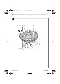
Routing with Guide Bushing (see figures K – N)
The guide bushing
47
enables template and pattern routing
on workpieces.
In order to use the guide bushing
47
, the guide bushing adapt-
er
44
must be inserted into the guide plate
9
first.
Place the guide bushing adapter
44
from above onto the
guide plate
9
and tighten it firmly with the 2 fastening screws
45
. Pay attention that the release lever for the guide bushing
adapter
46
is freely movable.
OBJ_BUCH-203-004.book Page 19 Wednesday, November 23, 2011 9:50 AM
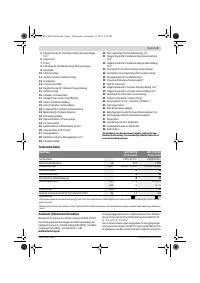
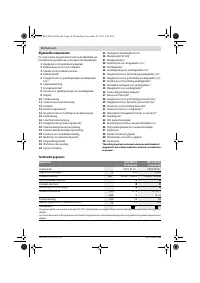
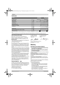
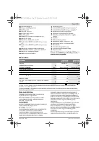
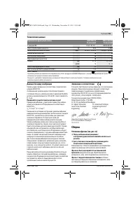
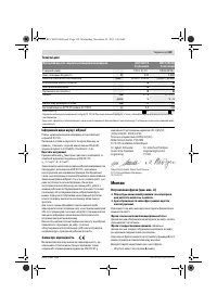
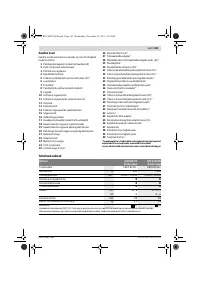
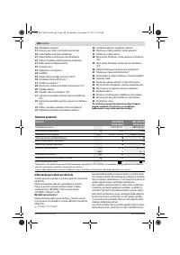
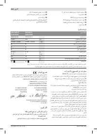
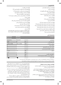
Характеристики

Остались вопросы?Не нашли свой ответ в руководстве или возникли другие проблемы? Задайте свой вопрос в форме ниже с подробным описанием вашей ситуации, чтобы другие люди и специалисты смогли дать на него ответ. Если вы знаете как решить проблему другого человека, пожалуйста, подскажите ему :)


