
Вытяжки Falmec Lumen isola 120 - инструкция пользователя по применению, эксплуатации и установке на русском языке. Мы надеемся, она поможет вам решить возникшие у вас вопросы при эксплуатации техники.
Если остались вопросы, задайте их в комментариях после инструкции.
"Загружаем инструкцию", означает, что нужно подождать пока файл загрузится и можно будет его читать онлайн. Некоторые инструкции очень большие и время их появления зависит от вашей скорости интернета.


22
Phase
C1
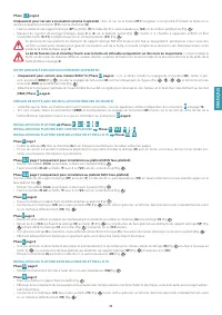
page 6
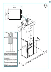
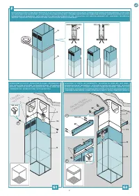
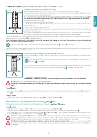
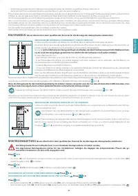
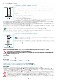
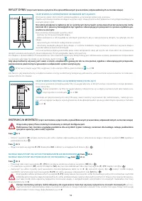
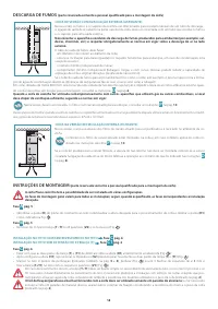
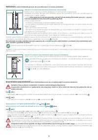
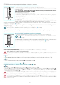
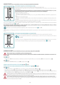
Only for version with external exhaust (suction):
if required by the selected height (
H1
), it is possible to install the hood using only the trellis (
T1
)
and the flue (
G
).
• Attach the extension supporting elements (
SP
) to the trellis (
T1
) using the 8 self-threading screws (
V4
) through the pre-drilled holes (Fig.
1
)
• Mark 4 drilling points on the ceiling (also identified on page
3
and
4
), drill (Fig.
2
) Put in 4 x ø 8mm expansion bolts and secure the
extension supporting elements (
SP
) to the ceiling by the relative screws (
V1
) (Fig.
3
).
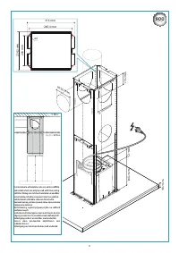
With false ceilings, the extension supporting elements (SP) must always be bolted to the false ceiling: said false ceiling must be reinforced
or somehow fitted with a solution that can guarantee safely attaching the hood to it, taking into account the strength of the used materi-
als and the weight of the hood (reported on page.
2
).
The fixing kit (screws and plugs) supplied with the hood can only be used on masonry walls:
should it be necessary to install the
hood onto walls in a different material, assess other fixing systems keeping the wall resistance and weight of the hood in mind (indicated
on page
2
).
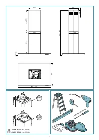
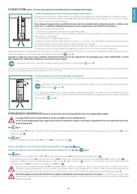
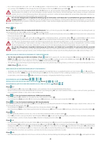
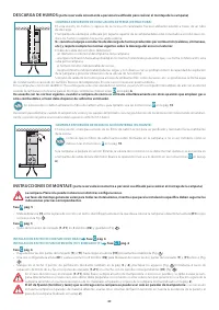
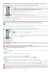
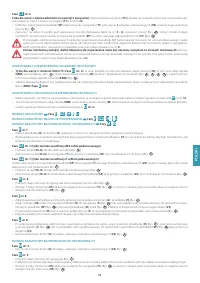
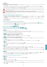
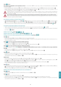
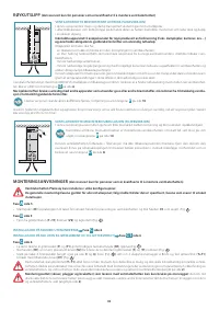
EXTERNAL EXHAUST HOOD VERSION (SUCTION)
• Only for the version with an 800m
3
/h
motor (
Phase
D
page 6
): if you wish, install the check valve (
M
); if the connection is installed (
ERM
)
take it down (Fig.
1
), install the check valve (
M
) as illustrated in the figures (Fig.
2
-
3
-
4
-
5
) and put the previously removed connection
back in (
ERM
) (Fig.
6
).
• Find the best length for the flexible (recommended) or rigid pipe to discharge the fumes and connect it suitably to the connection (
ERM
) (
Phase
E
page 6
).
HOOD VERSION WITH INTERNAL RECIRCULATION (FILTERING)
• Ensure that the active carbon filters are assembled onto the hood, if not, install them as indicated in the instructions
P
on page
10
.
• If installed, remove the connection (
ERM
) and any check valve (
M
) installed on the hood's air outlet fitting (perform, in reverse order, the opera-
tion described in the instructions
D
page 6
).
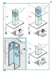
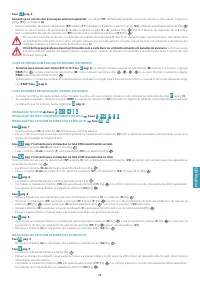
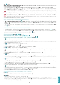
INSTALLATION ON CEILING
Phases
F
-
G1
-
H
-
I
-
L
INSTALLATION ON CEILING WITH FALSE CEILING
Phases
F
-
G2
-
H
-
I
-
L
INSTALLATION ON CEILING WITHOUT EXTENSION (H) AND TRELLIS (T)
Phases
M
-
N
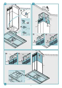
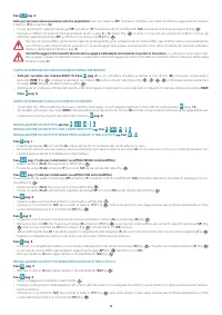
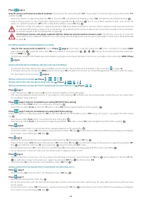
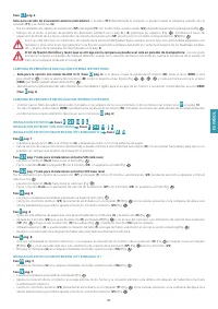
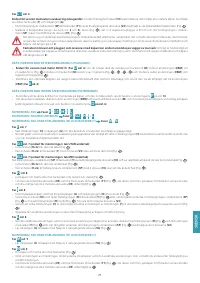
Phase
F
page 7
• Insert the extension (
H
) into the flue (
G
) and secure them together with masking tape.
• With external exhaust (suction) versions, it is possible to insert extension (
H
) with the slots facing downwards so that they are not visible when
the installation height allows it.
Phase
G1
page 7 (only for installations on ceiling WITHOUT false ceiling)
• Raise the assembly (
H+G
) until it is touching the ceiling (Fig.
1
).
• Attach the assembly (
H+G
) to the trellis (
T
) with 4 screws (
V3
) without tightening them all the way (Fig.
2
).
Phase
G2
page 7 (only for installations on ceiling WITH false ceiling)
Attach the extension supporting elements (
SP
) to the trellis (
T
) with 8 self-threading screws (
V4
) being sure to press it up against the false ceiling
Fig.
1
).
• Raise the assembly (
H+G
) until it is touching the false ceiling (Fig.
2
).
• Attach the assembly (
H+G
) to the extension supporting elements (
SP
) with 4 screws (
V3
) without tightening them all the way (Fig.
3
).
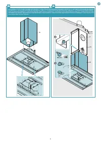
Phase
H
page 8
• Raise the hood so that it is near the trellis that is already attached to the ceiling (Fig.
1
).
• Centre the 4 metric screws, (
V5
) that are pre-screwed onto the trellis, (
T1
) (Fig.
2A
) on the holes on the hood; shift the hood sideways and tighten
the 4 metric screws definitively (
V5
) (Fig.
2B
).
Phase
I
page 8
• Remove the masking tape that was temporarily holding the flue (
G
) and extension (
H
) (Fig.
1
)
• Take out the 4 screws (
V3
) that attach the extension (
H
) to the trellis (
T
) (Fig.
2A
) or, with false ceilings, to the extension supporting elements (
SP
)
(Fig.
2B
) and slide the extension (
H
) downwards (Fig.
3
). Keep the removed (
V3
) screws.
• By lowering the extension (
H
) it is possible to connect the pipe (
F
) to the external discharge pipe (with the suction version)(Fig.
4
).
• Set up the electric connection only once the electric power supply has been cut off.
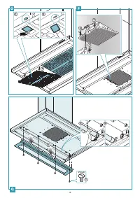
Phase
L
page 8
• When the electrical connection is set up, as well as the discharge connection, raise the extension (
H
) (Fig.
1
) and re-attach it to the trellis (
T
) (Fig.
2A
) or, with false ceilings, to the extension supporting elements (
SP
) (Fig.
2B
) by the 4 screws (
V3
).
• Attach the flue (
G
) to the hood by 2 self-threading screws (
V6
) (Fig.
3
).
INSTALLATION ON CEILING WITHOUT EXTENSION (H) AND TRELLIS (T)
Phase
M
page 9
• Attach the flue (
G
) to the hood by 2 self-threading screws (
V6
) (Fig.
1
).
Phase
N
page 9
• Raise the hood towards the trellis (Fig.
1
).
• Set up the connection with the external discharge pipe and the electrical connection, performing the latter after disconnecting the electrical
power supply.
• Centre the 4 metric screws, (
V5
) that are pre-screwed onto the trellis, (
T1
) (Fig.
2A
) on the holes on the hood; shift the hood sideways and tighten
the 4 metric screws definitively (
V5
) (Fig.
2B
).
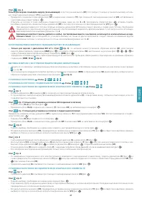
Содержание
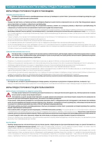
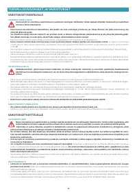
- 44 ТЕХНИКА БЕЗОПАСНОСТИ И МЕРЫ ПРЕДОСТОРОЖНОСТИ; МЕРЫ ПРЕДОСТОРОЖНОСТИ ДЛЯ УСТАНОВЩИКА; ТЕХНИКА БЕЗОПАСНОСТИ; ЭЛЕКТРИЧЕСКАЯ БЕЗОПАСНОСТЬ; МЕРЫ ПРЕДОСТОРОЖНОСТИ ДЛЯ ПОЛЬЗОВАТЕЛЯ; МЕРЫ ПРЕДОСТОРОЖНОСТИ ОБЩЕГО ХАРАКТЕРА; Не пытаться самостоятельно; НАЗНАЧЕНИЕ
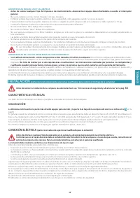
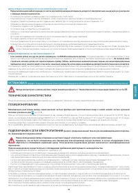
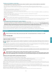
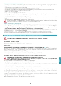
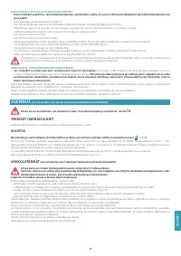
- 45 СИЙ; МЕРЫ ПРЕДОСТОРОЖНОСТИ ПО ЭКСПЛУАТАЦИИ И ОЧИСТКЕ; УСТАНОВКА; ТЕХНИЧЕСКИЕ ХАРАКТЕРИСТИКИ; вытяжки указано на рис.; ПОДК ЛЮЧЕНИЕ К СЕТИ ЭЛЕКТРОПИТАНИЯ; (раздел, предназначенный только для квалифицированного персона-
- 46 ОТВОД ДЫМОВ; КУХОННАЯ ВЫТЯЖКА В ВЕРСИИ С ВЫВОДОМ НАРУЖУ (ВСАСЫВАЮЩАЯ); ИНСТРУКЦИИ ПО МОНТАЖУ; Этап
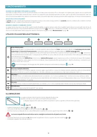
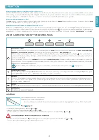
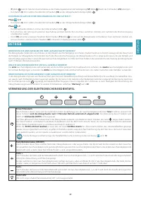
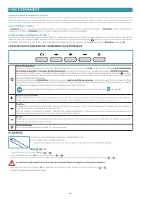
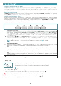
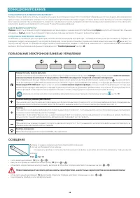
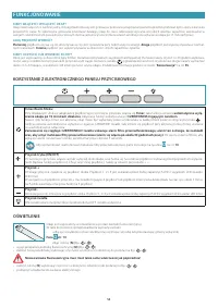
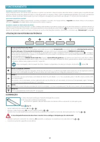
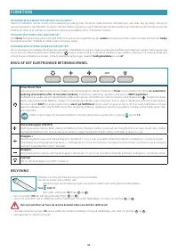
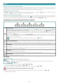
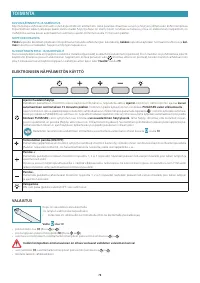
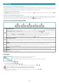
- 48 ФУНКЦИОНИРОВАНИЕ; КОГДА ВК ЛЮЧАТЬ И ВЫК ЛЮЧАТЬ ВЫТЯЖКУ?; ПОЛЬЗОВАНИЕ ЭЛЕКТРОННОЙ ПАНЕЛЬЮ УПРАВЛЕНИЯ
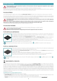
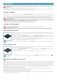
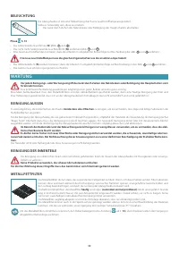
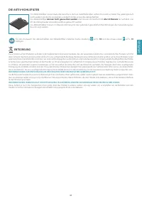
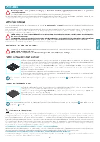
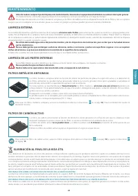
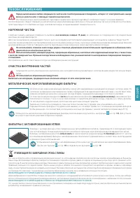
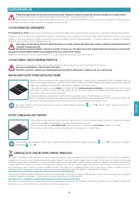
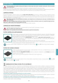
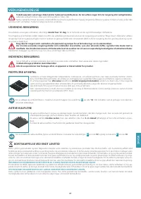
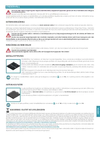
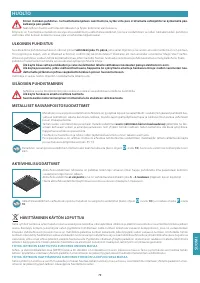
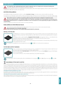
- 49 ТЕХОБС ЛУЖИВАНИЕ; НАРУЖНАЯ ЧИСТКА; НЕ пользоваться абразивными продуктами.; МЕТАЛЛИЧЕСКИЕ ЖИРОУЛАВЛИВАЮЩИЕ ФИЛЬТРЫ; часто; ФИЛЬТРЫ С АКТИВИРОВАННЫМ УГЛЕМ; нельзя мыть; УТИЛИЗАЦИЯ ПО ЗАВЕРШЕНИИ СРОКА СЛУЖБЫ; ИНФОРМАЦИЯ ПО У ТИЛИЗАЦИИ В СТРАНАХ EВРОПЕЙСКОГО CОЮЗА
Характеристики

Остались вопросы?Не нашли свой ответ в руководстве или возникли другие проблемы? Задайте свой вопрос в форме ниже с подробным описанием вашей ситуации, чтобы другие люди и специалисты смогли дать на него ответ. Если вы знаете как решить проблему другого человека, пожалуйста, подскажите ему :)


