
Варочная панель DeLonghi I 23-1 ER RUS - инструкция пользователя по применению, эксплуатации и установке на русском языке. Мы надеемся, она поможет вам решить возникшие у вас вопросы при эксплуатации техники.
Если остались вопросы, задайте их в комментариях после инструкции.
"Загружаем инструкцию", означает, что нужно подождать пока файл загрузится и можно будет его читать онлайн. Некоторые инструкции очень большие и время их появления зависит от вашей скорости интернета.


32
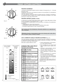
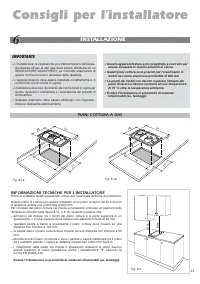
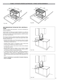
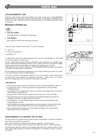
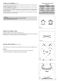
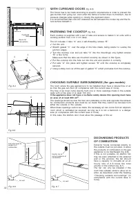
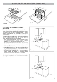
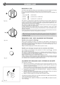
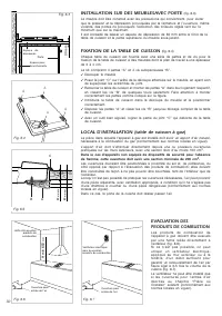
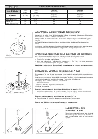
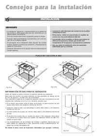
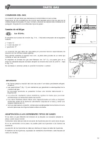
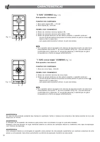
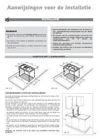
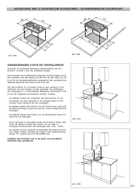
CHOOSING SUITABLE SURROUNDINGS (for gas models)
The room where the gas appliance is to be installed must have a natural flow of air
so that the gas can burn (in compliance with the current laws in force).
The flow of air must come directly from one or more openings made in the outside
walls with a free area of at least 100 cm
2
.
If the appliance does not have a no-flame safety device this opening must have
an area of at least 200 cm
2
.
The openings should be near the floor and preferably on the side opposite the exhaust
for combustion products and must be so made that they cannot be blocked from
either the outside or the outside.
When these openings cannot be made, the necessary air can come from an adjacent
room which is ventilated as required, as long as it is not a bedroom or a danger
area (in compliance with the current laws in force).
In this case, the kitchen door must allow the passage of the air.
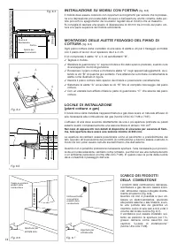
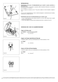
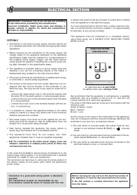
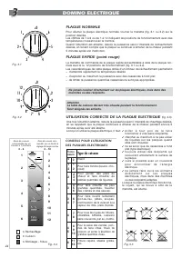
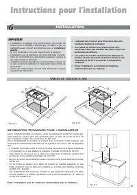
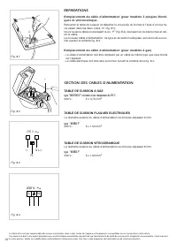
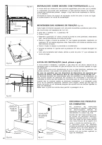
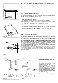
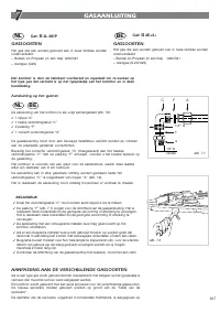
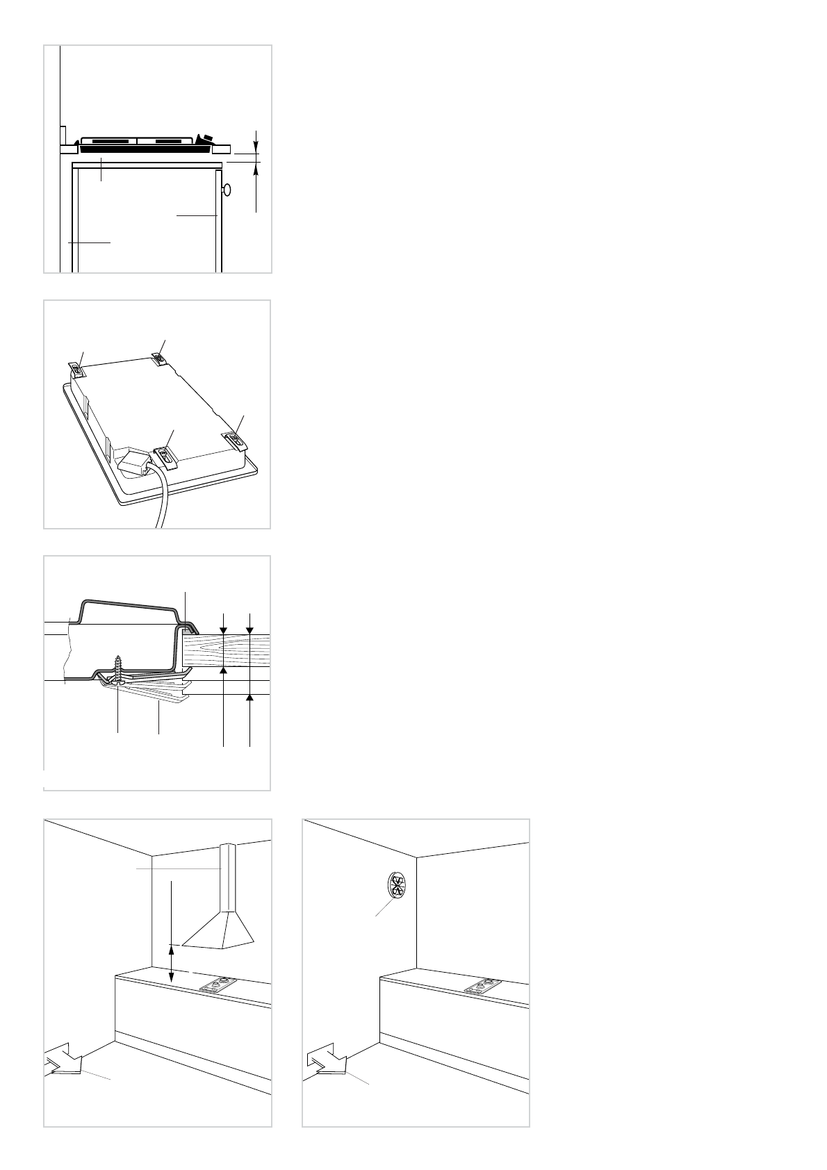
DISCHARGING PRODUCTS
OF COMBUSTION
Extractor hoods connected directly to
the outside must be provided, to allow
the products of combustion in the gas
appliance to be discharged (fig. 6.6).
If this is not possible, an electric fan
may be used, attached to the external
wall or the window; the fan should
have a capacity to circulate air at an
h o u r l y r a t e o f 3 - 5 t i m e s t h e t o t a l
volume of the kitchen (fig. 6.7).
The fan can only be installed if the
room has suitable vents to allow air to
enter, as described under the heading
“Choosing suitable surroundings” (in
compliance with the current laws in
force).
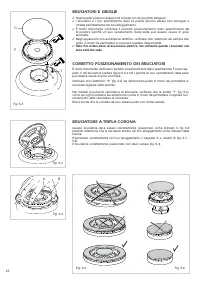
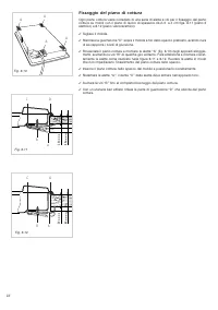
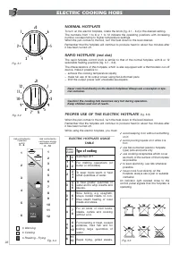
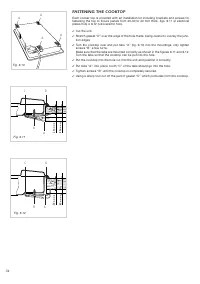
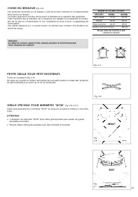
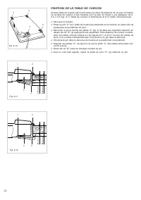
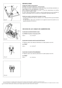
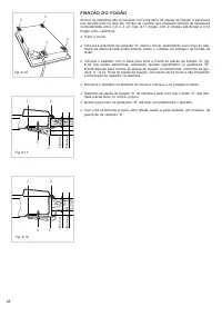
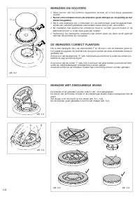
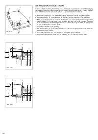
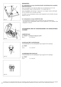
FASTENING THE COOKTOP
(fig. 6.4)
Each cooktop is supplied with a set of tabs and screws to fasten it on units with a
working surface from 2 to 4 cm deep.
The kit includes 4 tabs “A” and 4 self-threading screws “B”.
✓
Cut the unit.
✓
Stretch gasket “C” over the edge of the hole made, being careful to overlay the
junction edges.
✓
Turn the cooktop over and put tabs “A” into the mountings; only tighten screws
“B” a few turns.
Make sure that the tabs are mounted correctly as shown in the figure.
✓
Put the cooktop into the hole cut into the unit and position it correctly.
✓
Put tabs “A” into place and tighten screws “B” until the cooktop is completely
secured.
✓
Using a sharp tool cut off the part of gasket “C” which protrudes from the cooktop.
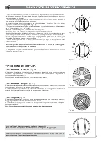
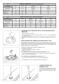
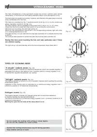
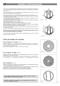
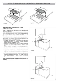
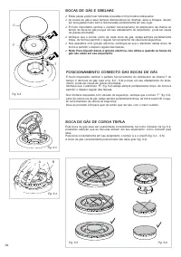
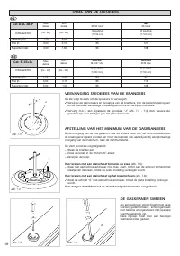
WITH CUPBOARD DOORS
(fig. 6.3)
The fixture has to be made according to specific requirements in order to prevent the
gas burners from going out, even when the flame is turned down to minimum, due to
pressure changes while opening or closing the cupboard doors.
It is recommended that a 30 mm clearance be left between the cooker top and the fix-
ture surface beneath it.
;;
;
;;
;
;
;
;
;
@
@
@
@
@
;
;
;
;
;
@
@
@
@
@
;
;
;
;
;
@
@
@
@
@
;
;
;
;
;
@
@
@
@
@
;
;
;
;
;
@
@
@
@
@
;
;
;
;
;
@
@
@
@
@
;
;
;
;
;
@
@
@
@
@
;
;
;
;
;
@
@
@
@
@
;
;
;
;
;
@
@
@
@
@
;
;
;
;
;
@
@
@
@
@
;
;
;
;
;
@
@
@
@
@
;
;
;
;
;
@
@
@
@
@
;
;
;
;
;
@
@
@
@
@
;
;
;
;
;
@
@
@
@
@
;
;
;
;
;
@
@
@
@
@
;
;
;
;
;
@
@
@
@
@
;
;
;
;
;
@
@
@
@
@
;
;
;
;
;
@
@
@
@
@
;
;
;
;
;
@
@
@
@
@
;
;
;
;
;
@
@
@
@
@
;
;
;
;
;
@
@
@
@
@
;
;
;
;
;
@
@
@
@
@
;
;
;
;
;
@
@
@
@
@
;
;
;
;
;
;;;;;;;
;;;;;
;;;;;
30 mm
Fig. 6.3
Space for
connections
Clearance
Cupboard
door
H min 650
mm
Fig. 6.6
Air vent
Extractor hood for
products of
combustion
Fig. 6.7
Air vent
Electric fan to
extract products of
combustion
Fig. 6.4
A
A
A
A
20
mm min.
40
mm max.
B
C
A
Fig. 6.5


