
Триммеры CROWN CT20051 - инструкция пользователя по применению, эксплуатации и установке на русском языке. Мы надеемся, она поможет вам решить возникшие у вас вопросы при эксплуатации техники.
Если остались вопросы, задайте их в комментариях после инструкции.
"Загружаем инструкцию", означает, что нужно подождать пока файл загрузится и можно будет его читать онлайн. Некоторые инструкции очень большие и время их появления зависит от вашей скорости интернета.


15
English
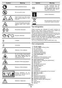
33
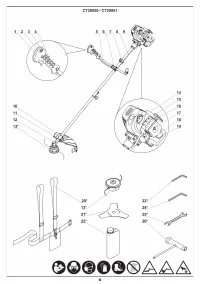
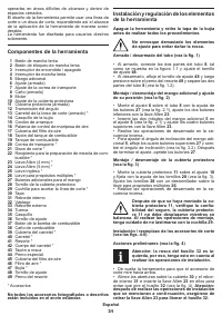
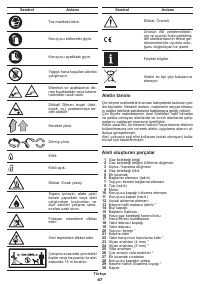
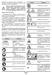
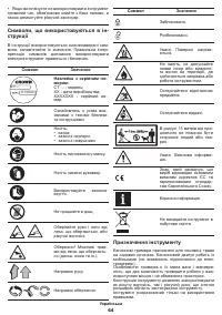
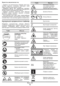
Outer flange
34
Nut
35
Cap
36
Clamping screw
37
Fuel pump button
38
Fuel pipe
39
Spool cover *
40
Spool *
41
Spring *
42
Spool body *
43
Screw cap
44
Special bolt
45
Air filter cap
46
Air filter *
47
Spark plug *
48
Clamping screw
49
Spring pin
* Optional extra
Not all of the accessories illustrated or described
are included as standard delivery.
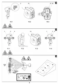
Installation and regulation of tool ele
-
ments
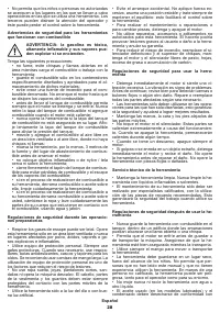
Switch off the tool and remove the cap from the
spark plug before fulfilling all procedures.
Do not draw up the fastening elements
too tight to avoid damaging the thread.
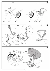
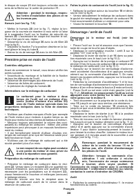
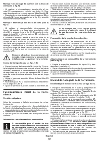
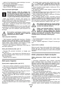
Assembling / disassemling of the tube (see fig. 1)
•
When assembling, connect the two parts of the
tube
8
, as shown in figure 1.1, and tighten the clamping
screw
48
�
•
When disassembling, loosen the clamping screw
48
,
and then press on the spring pin
49
and separate the
two parts of the tube
8
(see fig. 1.2).
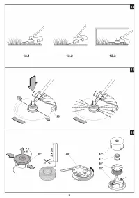
Mounting / demounting of the additional handle
and adjusting of its position (see fig. 2)
•
Mount fastening
6
on tube
8
with the help of bolts
27
(see fig. 2.1), tighten two lower bolts with a Allen key
23
�
•
Insert two halves of additional handle
5
into
fastening
6
(see fig. 2.1) and tighten four upper bolts
with the Allen key
23
�
•
Disassembly operations do in reverse sequence�
•
To adjust angle of inclination of additional handle
5
,
loosen four upper bolts
27
and change the angle of
inclination (see fig. 2.2). After finishing the adjustment
tighten bolts
27
�
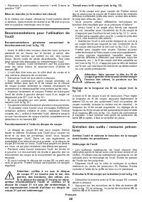
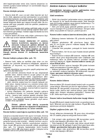
Mounting / demounting of the protective cover
(see fig. 3)
•
Mount protective cover
11
on fastening
10
and fix with
the help of screws
28
(see fig. 3). Tighten screws
28
with a screwdriver on multi-purpose wrench
26
�
•
Disassembly operations do in reverse sequence�
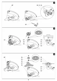
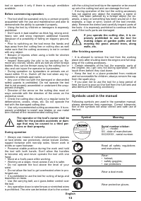
After the protective cover 11 is mounted,
check the latching reliability, the
protective cover 11 must not be displaced
while swinging it. When performing the
mounting operations, take care not to be injured
by knife 29.
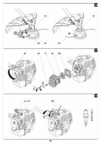
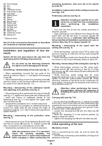
Installation / replacement of the cutting accessories
(see figs. 4-6)
Preliminary actions (see fig. 4)
Attention: treading on spindle 32 is a left-
hand one, so take this into consideration
when performing the installation
operations.
•
Turn over the tool so that the cutting accessory is
directed upwards�
•
Align openings on cover
30
and inner flange
31
and
insert Allen key
23
into them to prevent spindle
32
from rotating (see fig. 4).
Attention: after fulfilling the
below mentioned installation operations be sure to
remove Allen key 23 to release spindle 32.
Mounting / demounting of the spool with the
cutting line (see fig. 5)
•
When demounting, unscrew spool
13
by hand and
remove it (see fig. 5). After this remove outer flange
33
from spindle
32
�
•
When mounting, install outer flange
33
on spindle
32
(as shown on fig. 5) and manually screw on spool
13
�
Mounting / demounting of the cutting disc (see fig. 6)
•
When demounting, unscrew nut
34
, using multi-
purpose wrench
26
, and remove it (see fig. 6). After
this remove cap
35
, outer flange
33
and cutting disc
21
from spindle
32
�
•
When mounting, install cutting disc
21
, outer
flange
33
(as shown in fig. 6), cap
35
on spindle
32
and
tighten nut
34
with multi-purpose wrench
26
� When
mounting, direction of the arrow on the cutting disc
21
must always coincide with the direction of the arrow on
the protective cover
11
�
Attention: when performing the mount
-
ing operations, observe the sequence of
installing the parts and do not turn them
over.
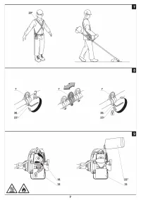
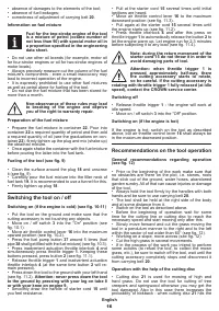
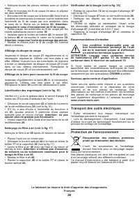
Carrying belt (see fig. 7-8)
•
Put on carrying belt
20
(see fig. 7), adjust the length
of the belt in such a way that you feel comfortable and
suspend the tool on the safety catch of carrying belt
20
�
The cutting accessory should touch the ground. If this
is not the case, make adjustment.
•
Loosen the clamping bolt
36
with the Allen key
23
(see fig. 8).
•
Move the fastening
7
to the desired position by
sliding it along the tube
8
�
•
Tighten the clamping bolt
36
with the Allen key
23
�
Initial operating of the tool
Mandatory check
Prior to commencing the work, be sure to check the
following:
•
correctness of mounting and reliability of fixing of all
elements of the tool;


