Триммеры Alpina B1.0EJ - инструкция пользователя по применению, эксплуатации и установке на русском языке. Мы надеемся, она поможет вам решить возникшие у вас вопросы при эксплуатации техники.
Если остались вопросы, задайте их в комментариях после инструкции.
"Загружаем инструкцию", означает, что нужно подождать пока файл загрузится и можно будет его читать онлайн. Некоторые инструкции очень большие и время их появления зависит от вашей скорости интернета.


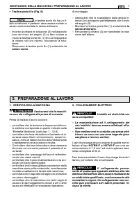
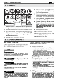
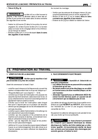
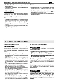


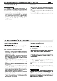


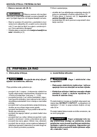
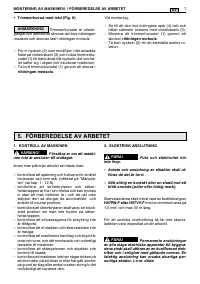
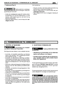
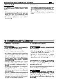


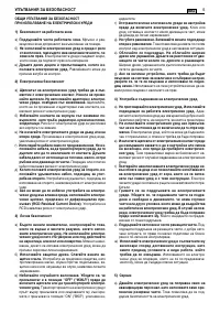


2. ELECTRICAL CONNECTIONS
Electricity and moisture
are not compatible.
– Always handle and connect electric cables
in dry conditions.
– Keep electric sockets or cables away from
wet and damp areas (e.g. puddles or wet
ground).
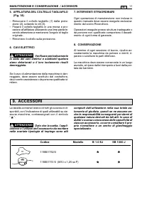
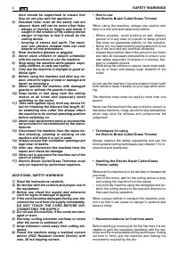
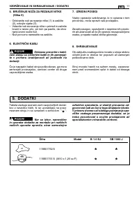
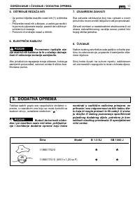
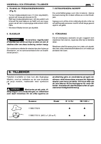
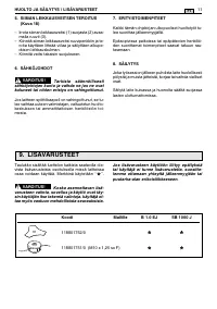
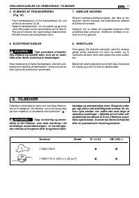
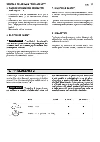
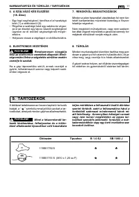
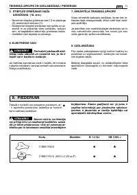
The quality of the extension leads must be no less
than
H07RN-F or H07VV-F
, with a minimum sec-
tion of 1.5 mm and a recommended maximum
length of 30 m.
To avoid overheating, do not keep the extension
lead rolled up during use.
The permanent connec-
tion of any electrical equipment to the mains of
a building must be installed by a qualified
electrician in conformity with the regulations in
force. Incorrect wiring can cause serious in-
jury and even death.
DANGER!
DANGER!
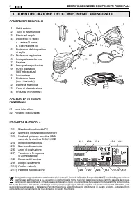
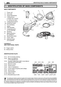
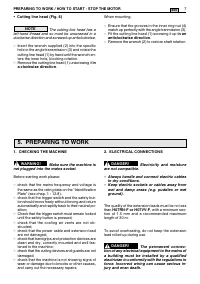
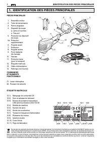
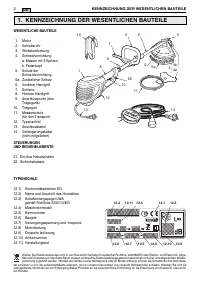
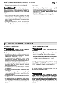
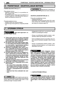
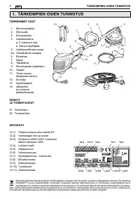
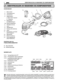
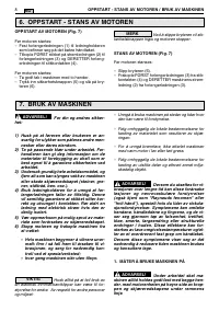
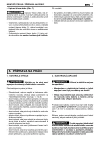
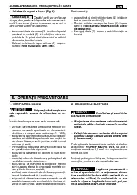
1. CHECKING THE MACHINE
Make sure the machine is
not plugged into the mains socket.
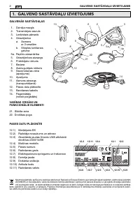
Before starting work please:
– check that the mains frequency and voltage is
the same as the rating data on the “Identification
Plate” (see chap. 1 - 12.8).
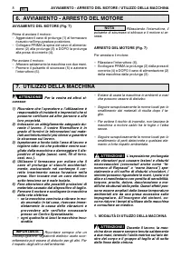
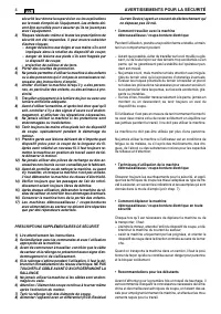
– check that the trigger switch and the safety but-
ton should move freely without forcing and return
automatically and rapidly back to their neutral po-
sition;
– Check that the trigger switch must remain locked
until the safety button is pressed;
– check that the cooling air vents are not ob-
structed;
– check that the power cable and extension lead
are not damaged;
– check that handgrips and protection devices are
clean and dry, correctly mounted and well fas-
tened to the machine;
– check that the cutting devices and guards are not
damaged;
– check that the machine is not showing signs of
wear or damage due to knocks or other causes,
and carry out the necessary repairs.
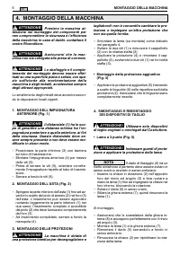
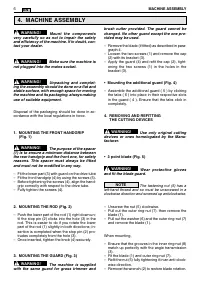
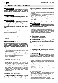
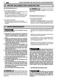
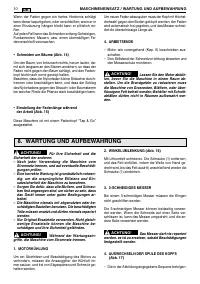
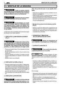
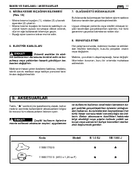
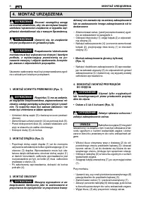
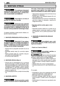
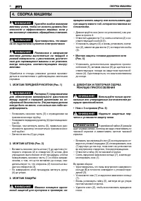
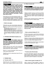
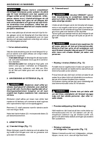
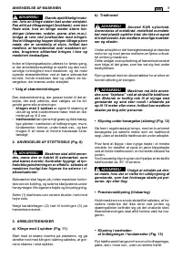
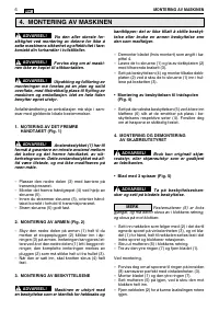
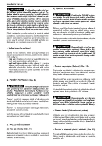
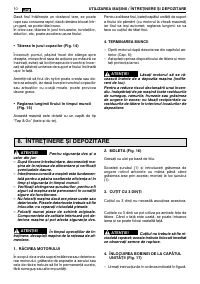
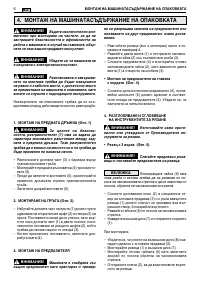
WARNING!
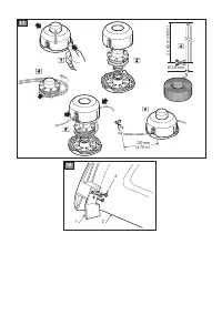
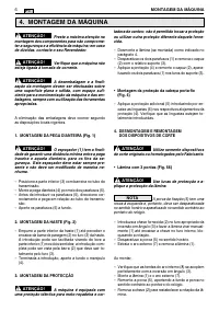
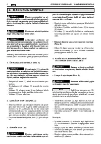
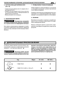
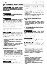
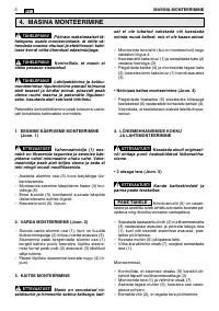
When mounting,
– Ensure that the grooves in the inner ring-nut (4)
match up perfectly with the angle tranmission (3).
– Fit the cutting line head (1) screwing it up
in an
anticlockwise direction
.
– Remove the wrench (2) to restore shaft rotation.
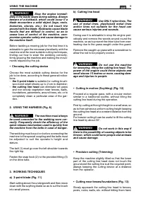
• Cutting line head (Fig. 6)
The cutting line head has a
left-hand thread and so must be unscrewed in a
clockwise direction and screwed up anticlockwise.
– Insert the wrench supplied (2) into the specific
hole in the angle transmission (3) and rotate the
cutting line head (1) by hand until the wrench en-
ters the inner hole, blocking rotation.
– Remove the cutting line head (1) unscrewing it
in
a clockwise direction
.
NOTE
PREPARING TO WORK / HOW TO START - STOP THE MOTOR
7
EN
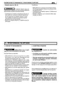
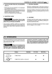
5. PREPARING TO WORK
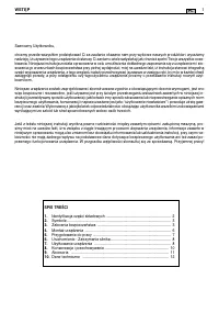
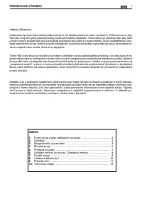
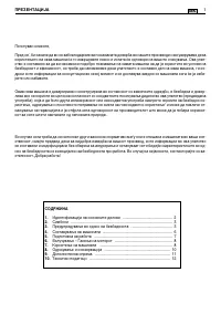
Содержание
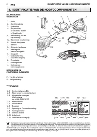
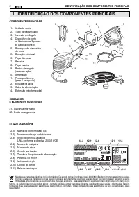
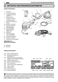
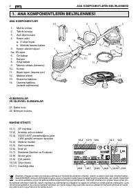
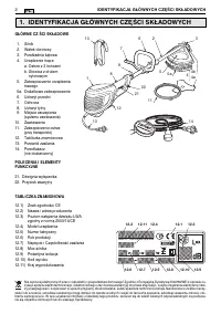
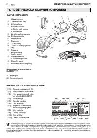
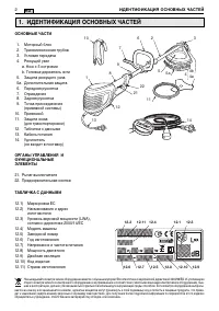
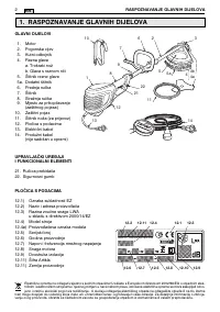
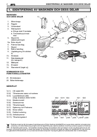
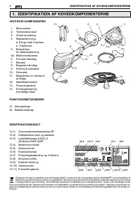
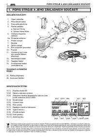
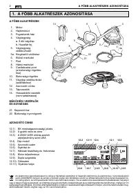
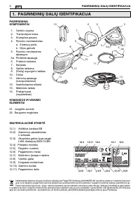
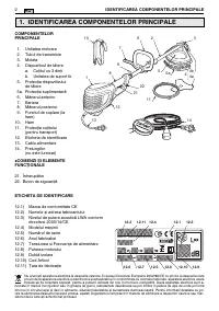
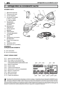
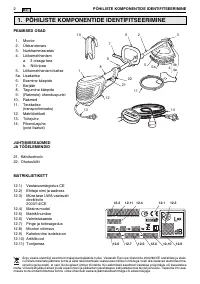
- 140 ИДЕНТИФИKАЦИЯ ОСНОВНЫХ ЧАСТЕЙ
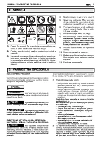
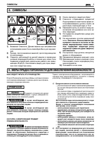
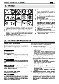
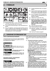
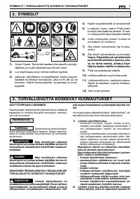
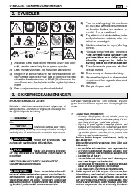
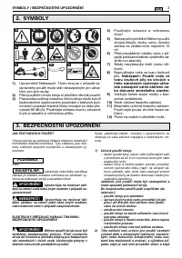
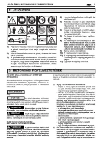
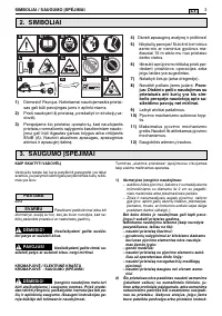
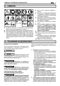
- 141 МЕРЫ ПРЕДОСТОРОЖНОСТИ ДЛЯ ОБЕСПЕЧЕНИЯ БЕЗОПАСНОСТИ
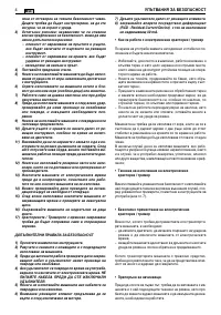
- 142 МЕРЫ ПРЕДОСТОРОЖНОСТИ ДЛЯ ОБЕСПЕЧЕНИЯ БЕЗОПАСНОСТИ
- 144 ПРИМЕЧАНИЕ
- 145 ПОДГОТОВKА K РАБОТЕ; по часовой стрелке
- 146 ПОЛЬЗОВАНИЕ МАШИНОЙ
- 148 ТЕХОБСЛУЖИВАНИЕ И ХРАНЕНИЕ
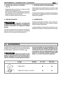
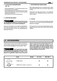
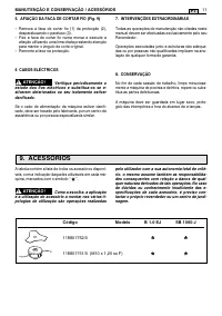
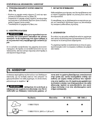
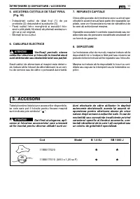
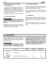
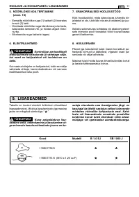
- 149 ДОПОЛНИТЕЛЬНЫЕ ПРИСПОСОБЛЕНИЯ
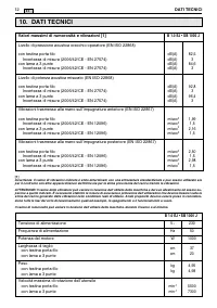
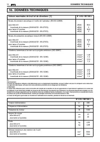
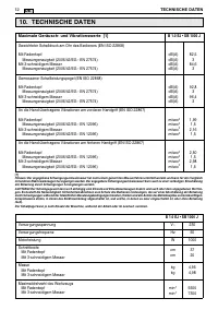
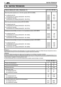
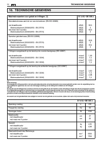
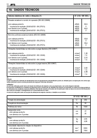
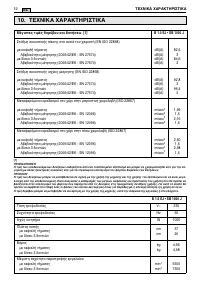
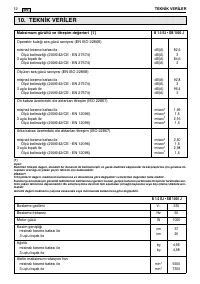
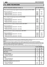
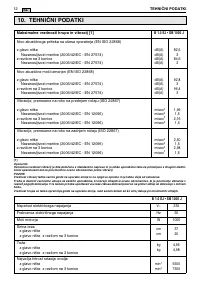
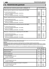
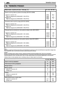
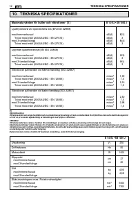
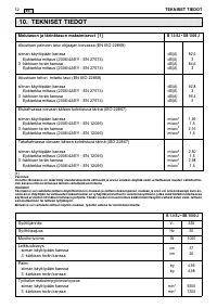
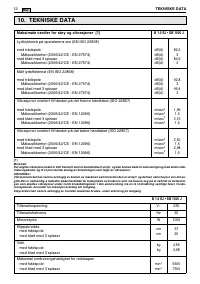
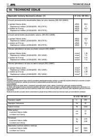
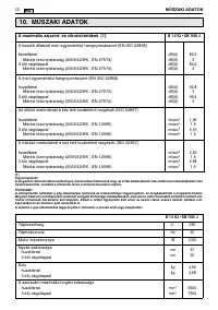
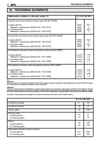
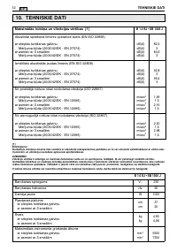
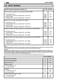
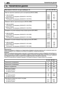
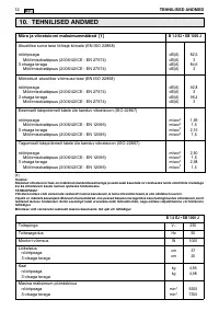
- 150 ТЕХНИЧЕСКИЕ ДАННЫЕ
Характеристики

Остались вопросы?Не нашли свой ответ в руководстве или возникли другие проблемы? Задайте свой вопрос в форме ниже с подробным описанием вашей ситуации, чтобы другие люди и специалисты смогли дать на него ответ. Если вы знаете как решить проблему другого человека, пожалуйста, подскажите ему :)


