Триммеры Alpina B1.0EJ - инструкция пользователя по применению, эксплуатации и установке на русском языке. Мы надеемся, она поможет вам решить возникшие у вас вопросы при эксплуатации техники.
Если остались вопросы, задайте их в комментариях после инструкции.
"Загружаем инструкцию", означает, что нужно подождать пока файл загрузится и можно будет его читать онлайн. Некоторые инструкции очень большие и время их появления зависит от вашей скорости интернета.


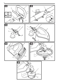

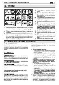


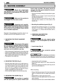
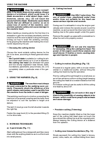

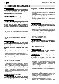


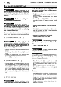


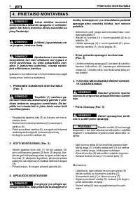

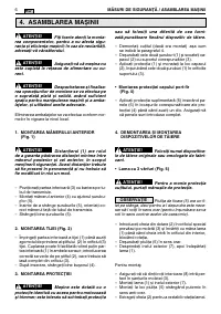


brush cutter provided. The guard cannot be
changed. No other guard except the one pro-
vided may be used.
– Remove the blade (if fitted) as described in para-
graph 4.
– Loosen the two screws (1) and remove the cap
(2) with its bracket (3).
– Apply the guard (4) and refit the cap (2), tight-
ening the two screws (1) in the holes in the
bracket (3).
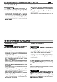
• Mounting the additional guard (Fig. 4)
– Assemble the additional guard ( 5 ) by clicking
the tabs ( 6 ) into place in their respective slots
in the guard ( 4 ). Ensure that the tabs click in
completely.
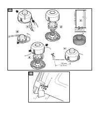
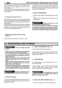
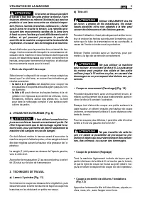
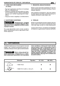
4. REMOVING AND REFITTING
THE CUTTING DEVICES
Use only original cutting
devices or ones homologated by the Manu-
facturer.
• 3 point blade (Fig. 5)
Wear protective gloves
and fit the blade guard.
The fastening nut (5) has a
left-hand thread and so must be unscrewed in a
clockwise direction and screwed up anticlockwise.
– Unscrew the nut (5) clockwise.
– Pull out the outer ring-nut (7), then remove the
blade (1).
– Pull out the washer (6) and the outer ring-nut (7)
and remove the blade (1).
When mounting,
– Ensure that the grooves in the inner ring-nut (8)
match up perfectly with the angle transmission
(3).
– Fit the blade (1) and outer ring-nut (7).
– Refit the nut (5) fully tightening it in an anti-clock-
wise direction.
– Remove the wrench (2) to restore blade rotation.
NOTE
WARNING!
WARNING!
Mount the components
very carefully so as not to impair the safety
and efficiency of the machine. If in doubt, con-
tact your dealer.
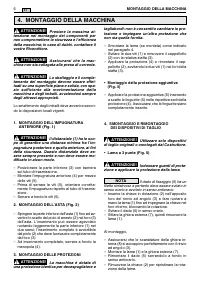
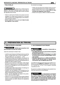
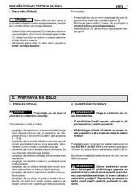
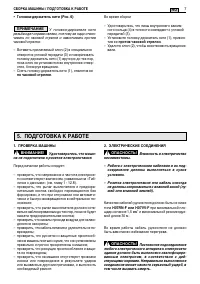
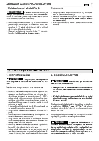
Make sure the machine is
not plugged into the mains socket.
Unpacking and complet-
ing the assembly should be done on a flat and
stable surface, with enough space for moving
the machine and its packaging, always making
use of suitable equipment.
Disposal of the packaging should be done in ac-
cordance with the local regulations in force.
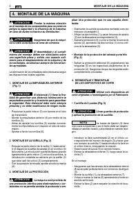
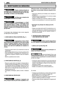
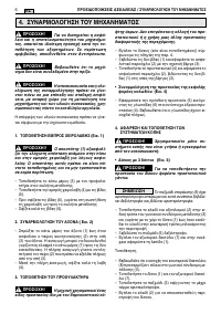
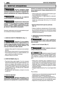
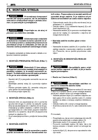
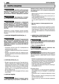
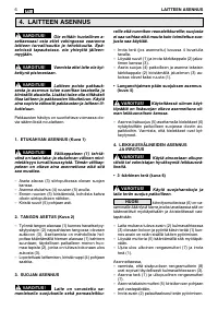
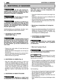
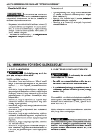
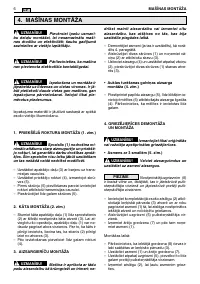
1. MOUNTING THE FRONT HANDGRIP
(Fig. 1)
The purpose of the spacer
(1) is to ensure a minimum distance between
the rear handgrip and the front one, for safety
reasons. This spacer must always be fitted
and must not be modified in any way.
– Fit the lower part (3) with guard on the drive tube
– Fit the front handgrip (4) by using the screws (5).
– Before tightening the screws (4), align the hand-
grip correctly with respect to the drive tube.
– Fully tighten the screws (4).
2. MOUNTING THE ROD (Fig. 2)
– Push the lower part of the rod (1) right down un-
til the stop pin (2) clicks into the hole (3) in the
rod. This is easier to do if you rotate the lower
part of the rod (1) slightly in both directions; in-
sertion is completed when the stop pin (2) pro-
trudes completely from the hole (3).
– Once inserted, tighten the knob (4) securely.
3. MOUNTING THE GUARD (Fig. 3)
The machine is supplied
with the same guard for grass trimmer and
WARNING!
WARNING!
WARNING!
WARNING!
WARNING!
6
MACHINE ASSEMBLY
EN
4. MACHINE ASSEMBLY
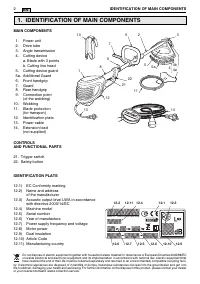
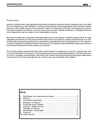
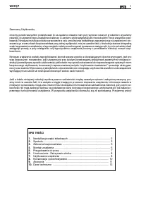
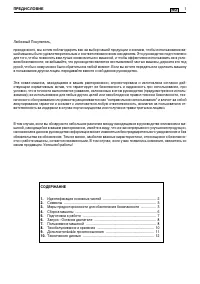
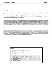
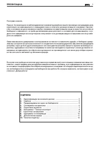
Содержание
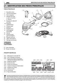
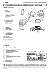
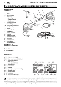
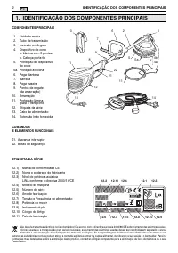
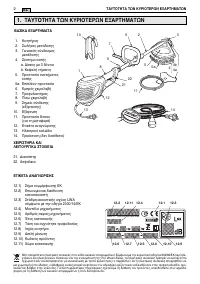
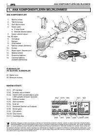
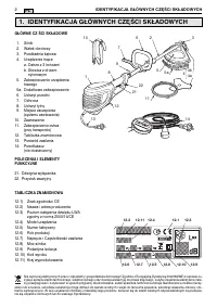
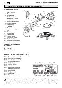
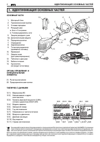
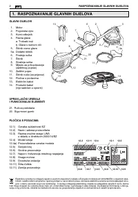
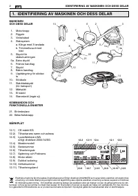
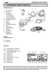
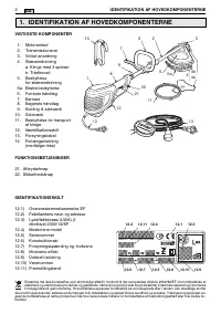
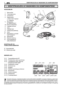
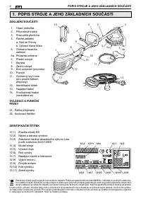
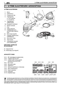
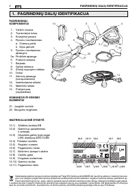
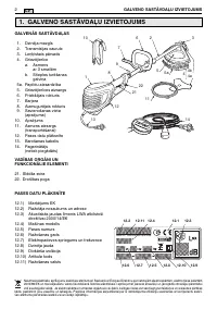
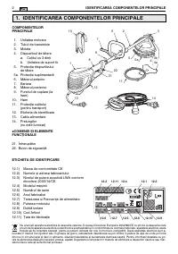
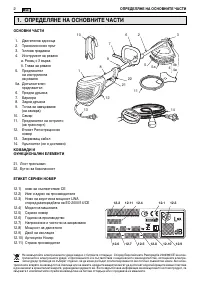
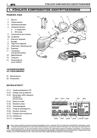
- 140 ИДЕНТИФИKАЦИЯ ОСНОВНЫХ ЧАСТЕЙ
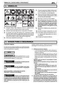
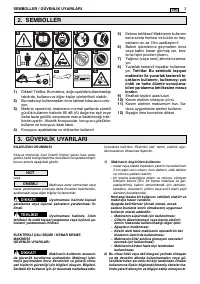
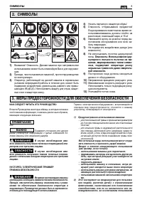
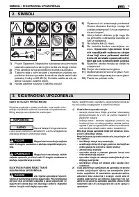
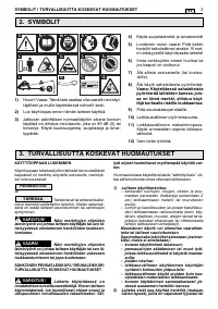
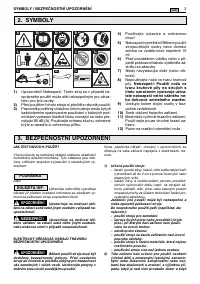
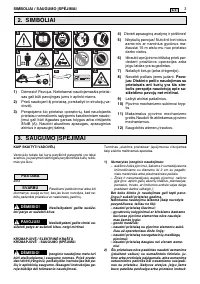
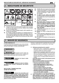
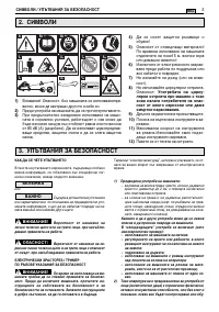
- 141 МЕРЫ ПРЕДОСТОРОЖНОСТИ ДЛЯ ОБЕСПЕЧЕНИЯ БЕЗОПАСНОСТИ
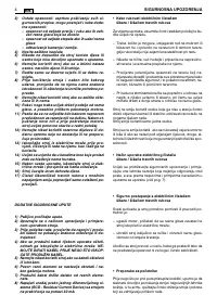
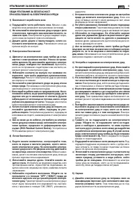
- 142 МЕРЫ ПРЕДОСТОРОЖНОСТИ ДЛЯ ОБЕСПЕЧЕНИЯ БЕЗОПАСНОСТИ
- 144 ПРИМЕЧАНИЕ
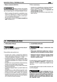
- 145 ПОДГОТОВKА K РАБОТЕ; по часовой стрелке
- 146 ПОЛЬЗОВАНИЕ МАШИНОЙ
- 148 ТЕХОБСЛУЖИВАНИЕ И ХРАНЕНИЕ
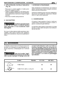
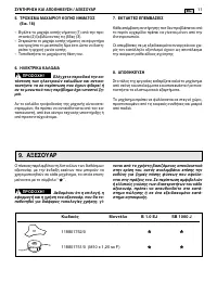
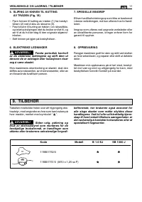
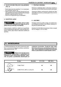
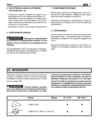
- 149 ДОПОЛНИТЕЛЬНЫЕ ПРИСПОСОБЛЕНИЯ
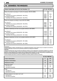
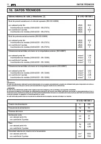
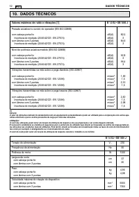
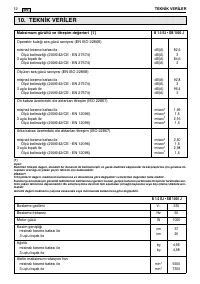
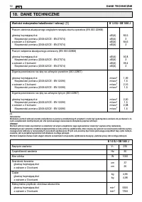
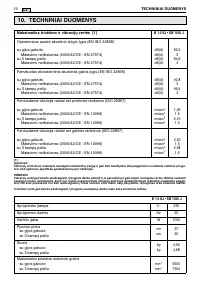
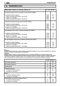
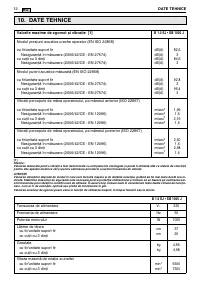
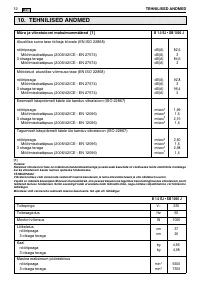
- 150 ТЕХНИЧЕСКИЕ ДАННЫЕ
Характеристики

Остались вопросы?Не нашли свой ответ в руководстве или возникли другие проблемы? Задайте свой вопрос в форме ниже с подробным описанием вашей ситуации, чтобы другие люди и специалисты смогли дать на него ответ. Если вы знаете как решить проблему другого человека, пожалуйста, подскажите ему :)


