Измерительные приборы Bosch GMS 100 - инструкция пользователя по применению, эксплуатации и установке на русском языке. Мы надеемся, она поможет вам решить возникшие у вас вопросы при эксплуатации техники.
Если остались вопросы, задайте их в комментариях после инструкции.
"Загружаем инструкцию", означает, что нужно подождать пока файл загрузится и можно будет его читать онлайн. Некоторые инструкции очень большие и время их появления зависит от вашей скорости интернета.


English |
11
Bosch Power Tools
1 609 929 Y44 | (10.5.11)
Operation
f
Protect the measuring tool against moisture and direct
sun light.
f
Do not subject the measuring tool to extreme tempera-
tures or variations in temperature. In case of large var-
iations in temperature, allow the measuring tool to ad-
just to the ambient temperature before switching it on.
In case of extreme temperatures or variations in tempera-
ture, the accuracy of the measuring tool and the display in-
dication can be impaired.
f
Use or operation of transmitting systems, such as
WLAN, UMTS, radar, transmitter masts or microwaves,
in the close proximity can influence the measuring
function.
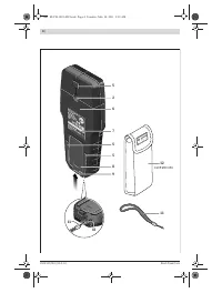
Initial Operation
Switching On and Off
f
Before switching the measuring tool on, make sure that
the sensor area 6 is not moist.
If required, dry the meas-
uring tool using a soft cloth.
f
If the measuring tool was subject to an extreme tem-
perature change, allow it to adjust to the ambient tem-
perature before switching on.
To
switch on
the measuring tool, press the On/Off button
4
.
To
switch off
the measuring tool, press the On/Off button
4
again.
When no button on the measuring tool is pressed for approx.
5 minutes and when no objects are detected, the measuring
tool automatically switches off to save the battery.
Switching the Audio Signal On/Off
When the measuring tool is switched on, the audio signal can
be switched on or off by pressing the On/Off button
4
for a few
seconds. When the audio signal is switched off, indication
a
appears on the display.
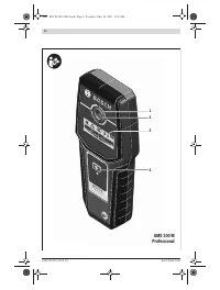
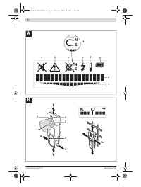
Method of Operation (see figures A – B)
The measuring tool checks the base material of sensor area
6
in measurement direction
z
to the max. detection depth (see
“Technical Data”). Objects are detected that differ from the
material of the wall.
Always move the measuring tool in a straight line over the sur-
face applying slight pressure, without lifting it off or changing
the pressure. During measurement, the contact pads
5
must
always have contact to the surface.
Measuring Procedure
After switching on, the illuminated ring
1
lights up green.
Position the measuring tool against the surface being detect-
ed and move it toward the
x
- and
y
-axis. When the measuring
tool comes closer to an object, the amplitude in the main scale
h
increases and ring
1
lights up yellow; when it is moved away
from the object, the amplitude decreases. The main scale
h
indicates the maximal amplitude above the object; ring
1
lights up red and an audio signal sounds. For small or deeply
embedded objects, ring
1
can continue to light up yellow,
while there is no audio signal.
f
Wide objects are not indicated by the illuminated ring
or the audio signal throughout their complete width.
As soon as the measuring tool has localised an object below
the centre of the sensor, the fine scale
i
is activated.
To localise the object more precisely, move the measuring
tool repeatedly (3 x) back and forth over the object.
The fine scale
i
indicates a maximum amplitude when the ob-
ject is positioned precisely below the centre of the sensor, in-
dependent thereof how many bars are displayed in the main
scale
h
.
When very small or deeply embedded objects are being sought
and main scale
h
reacts only slightly, move the measuring tool
repeatedly over the object in horizontal (
x
-axis) and vertical
(
y
-axis) direction. Observe the amplitude of fine scale
i
.
f
Before drilling, sawing or routing into a wall, protect
yourself against hazards by using other information
sources.
As the measuring results can be influenced
through ambient conditions or the wall material, there may
be a hazard even though the indicator does not indicate an
object in the sensor range (no audio signal or beep and and
the illuminated ring
1
lit green).
Metal
When the detected metal object is of magnetic metal (e. g.
iron), the symbol
d
is indicated on display
3
. For non-magnet-
ic metals, the symbol
c
is indicated. In order to differentiate
between metal types, the measuring tool must be positioned
above the detected metal object (ring
1
is lit red and fine scale
i
indicates a high amplitude).
Note:
For reinforcement steel mesh and steel in the examined
base material, an amplitude is indicated over the complete
surface of the main scale
h
. For reinforcement steel mesh, it
is typical that the symbol
d
for magnetic metal is indicated on
the display directly above the iron rods, whereas between the
iron rods, the symbol
c
for non-magnetic metal will appear.
Power Cable
When a “live” conductor is detected, indication
e
appears on
the display
3
. Move the measuring tool repeatedly over the
area to localise the “live” conductor more precisely. After
moving over the “live” conductor several times, it can be indi-
cated very accurately. When the measuring tool is very close
to the conductor, the illuminated ring
1
rapidly flashes red
and the audio signal beeps swiftly.
Notes:
– “Live” conductors can be detected easier when power con-
sumers (e. g. lamps, machines) are connected to the
sought conductor and switched on.
–
Under certain conditions (such as below metal surfaces
or behind surfaces with high water content), “live” con-
ductors cannot be securely detected.
The signal
strength of a “live” conductor depends on the position of
the cable. Therefore, apply further measurements in close
proximity or use other information sources to check if a
“live” conductor exists.
– Voltage-free conductors can be detected as metal objects.
This does not apply for stranded conductors (contrary to
solid conductors or cable).
– Static electricity can lead to inaccurate indication of elec-
tric lines, e. g., over a large range. To improve the indica-
tion, place your free hand flat on the wall next to the meas-
uring tool, in order to remove the static electricity.
OBJ_BUCH-1418-002.book Page 11 Tuesday, May 10, 2011 8:18 AM
Характеристики

Остались вопросы?Не нашли свой ответ в руководстве или возникли другие проблемы? Задайте свой вопрос в форме ниже с подробным описанием вашей ситуации, чтобы другие люди и специалисты смогли дать на него ответ. Если вы знаете как решить проблему другого человека, пожалуйста, подскажите ему :)


