
Фрезеры Bosch 0.601.626.000 - инструкция пользователя по применению, эксплуатации и установке на русском языке. Мы надеемся, она поможет вам решить возникшие у вас вопросы при эксплуатации техники.
Если остались вопросы, задайте их в комментариях после инструкции.
"Загружаем инструкцию", означает, что нужно подождать пока файл загрузится и можно будет его читать онлайн. Некоторые инструкции очень большие и время их появления зависит от вашей скорости интернета.


English |
19
Bosch Power Tools
1 609 92A 2NP | (19.8.16)
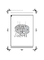
– Adjust the required depth-of-cut; see Section “Adjusting
the Depth-of-cut”.
– Place the machine with the router bit mounted on the
workpiece to be machined and switch the power tool on.
– Press the release lever
23
back and slowly guide the router
down until the router bit touches the workpiece surface.
Let go of the release lever
23
again to lock this plunging
depth.
– Carry out the routing process applying uniform feed.
– After finishing the cutting process, guide the plunge router
upward again to the uppermost position.
– Switch the power tool off.
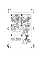
Routing with Auxiliary Guide (see figure G)
For working large workpieces, e. g. when routing grooves, a
board or wood strip can be fastened to the workpiece as an
auxiliary guide alongside which the router can be guided.
Guide the router with the flattened side of the guide plate
along the auxiliary guide.
Shaping or Molding Applications
For shaping or molding applications without the use of a par-
allel guide, the router bit must be equipped with a pilot or a
ball bearing.
– Guide the switched on power tool from the side toward the
workpiece until the pilot or the ball bearing of the router bit
faces against the workpiece edge to be machined.
– Guide the power tool alongside the workpiece edge with
both hands, paying attention that the router is positioned
rectangular. Too much pressure can damage the edge of
the workpiece.
Routing with Parallel Guide (see figure H)
Slide the parallel guide
33
with the rods
34
into the base plate
13
and tighten it with the screws
7
according to the required
dimension. You can also use the wing bolts
35
and
36
to set
the parallel guide lengthways.
Fine adjustment of the length is possible with the fine-adjust-
ment knob
37
after loosening both wing bolts
35
. One revolu-
tion corresponds with a setting range of 2.0 mm. One gradu-
ation mark on the fine-adjustment knob
37
changes the
setting range by 0.1 mm.
The effective contact surface of the parallel guide can be ad-
justed with the edge guide
38
.
Guide the switched on power tool with uniform feed and later-
al pressure on the parallel guide alongside the workpiece
edge.
When routing with the parallel guide
33
, dust/chip extraction
should be performed using the special extraction adapter
39
.
Routing with Circle Cutting Adapter (Accessory)
You can use the circle cutting adapter for circular routing
work.
Routing with Guide Rail (Accessory)
You can perform work in straight lines using the guide rail and
the guide rail adapter.
Routing with Guide Bushing (see figures I–L and figure N)
The guide bushing
43
enables template and pattern routing
on workpieces.
In order to use the guide bushing
43
, the guide bushing adapt-
er
40
must be inserted into the guide plate
11
first.
Place the guide bushing adapter
40
from above onto the
guide plate
11
and tighten it firmly with the 2 fastening
screws
41
. Pay attention that the release lever for the guide
bushing adapter
42
is freely movable.
Choose a suitable guide bushing, depending on the thickness
of the template or the pattern. Because of the projecting
height of the guide bushing, the template must have a mini-
mum thickness of 8 mm.
Actuate the release lever
42
and insert the guide bushing
43
from below into the guide bushing adapter
40
. Ensure that
the encoding keys clearly engage in the grooves of the guide
bushing.
Select a router bit with a diameter smaller than the in-
terior diameter of the guide bushing.
To ensure that the distance from router bit centre and guide
bushing edge is uniform, the guide bushing and the guide
plate can be adjusted to each other, if required.
– Press the release lever
23
back and guide the router all the
way towards the base plate
13
. Let go of the release lever
23
again to lock this plunging depth.
– Loosen the pan head screws
44
so that the guide plate
11
is freely movable.
– Insert the centring pin
45
into the tool holder as shown in
the figure. Hand-tighten the tightening nut so that the cen-
tring pin can still be moved freely.
– Align the guide bushing
43
with the centring pin by lightly
pushing the guide plate
11
.
– Tighten the pan head screws
44
.
– Remove the centring pin
45
from the tool holder.
– Push the release lever
23
and guide the plunge router to
the uppermost position.
For routing with the guide bushing
43
proceed as follows:
– Guide the switched on power tool with the guide bushing
toward the template.
– Press the release lever
23
back and slowly guide the router
down until the router bit touches the workpiece surface.
Let go of the release lever
23
again to lock this plunging
depth.
– Guide the switched on power tool with the protruding
guide bushing alongside the template applying lateral
pressure.
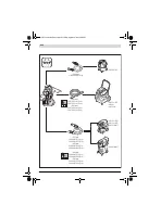
Changing the Battery (GOF 1250 LCE) (see figure M)
Slide the battery compartment cover
22
up and remove the
battery. Insert a new battery (type CR2032). The positive
pole of the battery must point forwards to the battery com-
partment cover
22
. Insert the seal
46
and close the battery
compartment cover
22
.
OBJ_BUCH-2018-005.book Page 19 Friday, August 19, 2016 9:44 AM
Характеристики

Остались вопросы?Не нашли свой ответ в руководстве или возникли другие проблемы? Задайте свой вопрос в форме ниже с подробным описанием вашей ситуации, чтобы другие люди и специалисты смогли дать на него ответ. Если вы знаете как решить проблему другого человека, пожалуйста, подскажите ему :)


