
Дрели Bosch 0.603.131.120 - инструкция пользователя по применению, эксплуатации и установке на русском языке. Мы надеемся, она поможет вам решить возникшие у вас вопросы при эксплуатации техники.
Если остались вопросы, задайте их в комментариях после инструкции.
"Загружаем инструкцию", означает, что нужно подождать пока файл загрузится и можно будет его читать онлайн. Некоторые инструкции очень большие и время их появления зависит от вашей скорости интернета.


English |
19
Bosch Power Tools
1 609 92A 2A0 | (17.11.16)
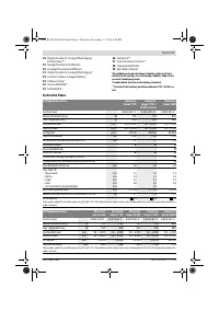
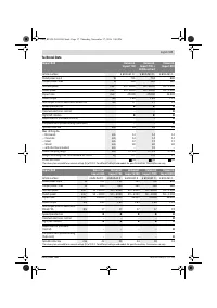
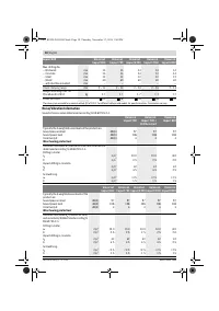
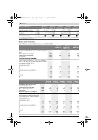
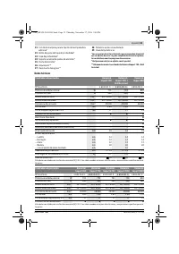
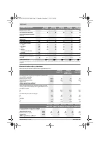
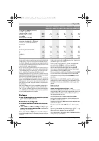
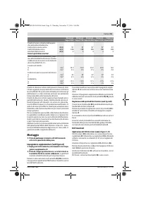
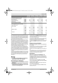
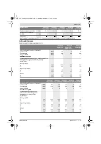
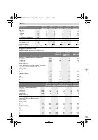
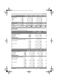
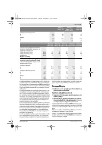
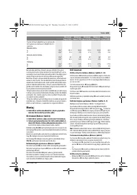
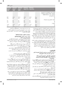
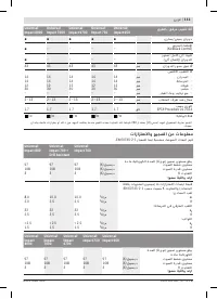
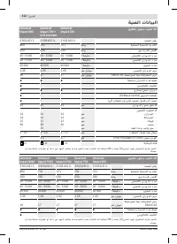
The vibration level given in this information sheet has been
measured in accordance with a standardised test given in
EN 60745 and may be used to compare one tool with anoth-
er. It may be used for a preliminary assessment of exposure.
The declared vibration emission level represents the main ap-
plications of the tool. However if the tool is used for different
applications, with different accessories or insertion tools or is
poorly maintained, the vibration emission may differ. This
may significantly increase the exposure level over the total
working period.
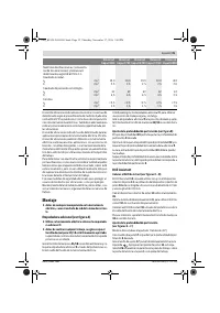
An estimation of the level of exposure to vibration should also
take into account the times when the tool is switched off or
when it is running but not actually doing the job. This may sig-
nificantly reduce the exposure level over the total working
period.
Identify additional safety measures to protect the operator
from the effects of vibration such as: maintain the tool and the
accessories, keep the hands warm, organisation of work pat-
terns.
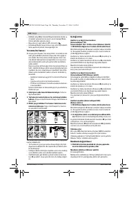
Assembly
Before any work on the machine itself, pull the mains
plug.
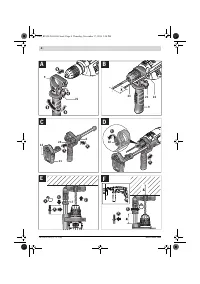
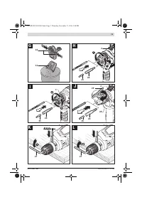
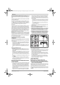
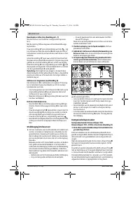
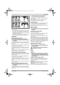
Auxiliary Handle (see figure A)
Operate your machine only with the auxiliary handle 9.
Before any work, make sure that the wing bolt 21/18 is
tightened.
Loss of control can cause personal injury.
Turn the wing bolt
21/18
counterclockwise and guide the
auxiliary handle
9
over the drill chuck onto the spindle collar
of the power tool.
You can swivel the auxiliary handle
9
in order to achieve a safe
work posture that minimises your fatigue.
Swivel the auxiliary handle
9
to the required position and
retighten the wing bolt
21/18
in clockwise direction.
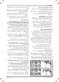
Adjusting the Drilling Depth (see figure B)
The required drilling depth
X
can be set with the depth stop
23
.
Press the button for depth stop adjustment
22
and insert the
depth stop into the auxiliary handle
9
.
The knurled surface of the depth stop
23
must face down-
ward.
Pull out the depth stop until the distance between the tip of
the drill bit and the tip of the depth stop corresponds with the
desired drilling depth
X
.
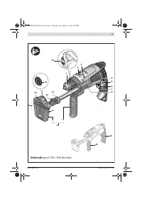
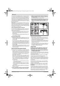
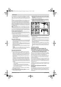
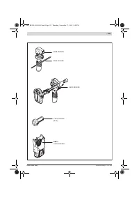
Drill Assistant
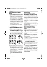
Attaching the Drill Assistant (see figures C – D)
The Drill Assistant
10
can be used with and without dust col-
lection device
13
. Use of the dust collection device
13
is lim-
ited to drill bits with a diameter of 12 mm and a length of
120 mm.
Attach the dust collection device
13
to the mounting
26
.
Press the unlocking button
8
to release the Drill Assistant
10
from its parked position.
Guide the Drill Assistant
10
over the drill chuck onto the spin-
dle collar of the power tool.
Lock it by turning the wing bolt
18
in clockwise direction.
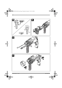
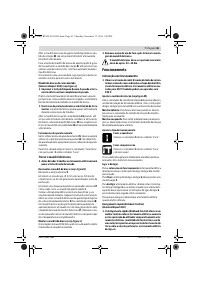
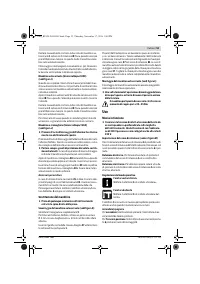
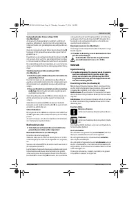
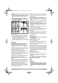
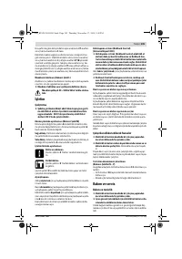
Adjusting the Drilling Depth (see figures E – F)
Mount the drill bit (see section “Changing the Tool”).
You can use the setting ring
17
to set the required drilling
depth
X
.
Unlock the setting ring
17
by turning it to the left
. Place
the dust box
11
or the mounting
26
flush against the wall or
workpiece. Move the tip of the drill bit to the wall or work-
piece.
Slide the setting ring
17
backward until the distance matches
the required drilling depth
X
or place a wall plug on the rail
and slide the setting ring
17
backward to the wall plug. Lock
the setting ring
17
by turning it to the right
. Take the wall
plug out of the rail again. The drilling depth now matches the
set length
X
on the rail.
Note:
It is important to have the exact drilling depth when us-
ing wall plugs. If the drilled hole is too deep, the wall plug will
slip too far into the wall or workpiece. If the hole is too small,
the wall plug will stick out.
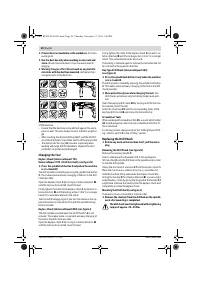
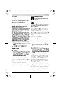
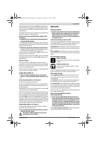
Emptying the Dust Box (see figure G)
The dust box
11
is enough for drilling about 25 holes in ma-
sonry at a drilling depth of 30 mm with a drill bit diameter of
6 mm.
– To remove the dust box
11
, press the side-mounted un-
locking buttons
12
and pull the dust box off in a downward
direction.
– Empty the dust box
11
and reinsert it (until it can be heard
to engage).
Removing the Drill Assistant
– Press and hold the clip
16
of the dust collection device
13
and pull the dust box
13
off toward the front.
– Turn the wing bolt
18
counterclockwise until the auxiliary
handle
9
can be moved and pull the auxiliary handle
9
off
the power tool.
– Unlock the setting ring
17
by turning it to the left
.
– Hold the auxiliary handle
9
in place and slide the rail to-
wards the auxiliary handle until it can be heard to engage.
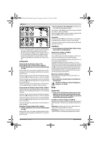
Dust Extraction/Dust Box
Dust from materials such as lead-containing coatings,
some wood types, minerals and metal can be harmful to
one’s health. Touching or breathing-in the dust can cause
allergic reactions and/or lead to respiratory infections of
the user or bystanders.
Certain dust, such as oak or beech dust, is considered car-
cinogenic, especially in connection with wood-treatment
additives (chromate, wood preservative). Materials con-
taining asbestos may only be worked by specialists.
– Use a dust extraction system suitable for the material
being worked.
– Provide for good ventilation of the working place.
– It is recommended to wear a P2 filter-class respirator.
Observe the relevant regulations in your country for the
materials to be worked.
OBJ_BUCH-2862-001.book Page 19 Thursday, November 17, 2016 2:40 PM
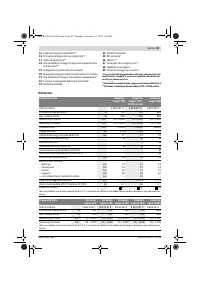
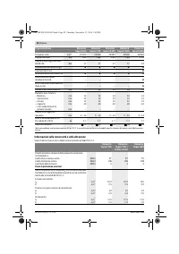
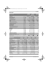
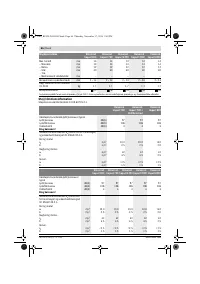
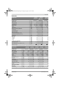
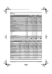
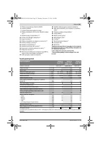
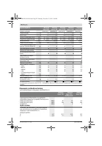
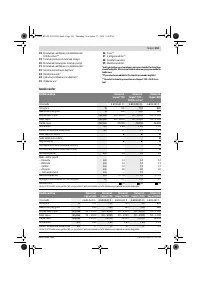
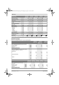
Характеристики

Остались вопросы?Не нашли свой ответ в руководстве или возникли другие проблемы? Задайте свой вопрос в форме ниже с подробным описанием вашей ситуации, чтобы другие люди и специалисты смогли дать на него ответ. Если вы знаете как решить проблему другого человека, пожалуйста, подскажите ему :)


