
Дрели Bosch 0.601.217.100 - инструкция пользователя по применению, эксплуатации и установке на русском языке. Мы надеемся, она поможет вам решить возникшие у вас вопросы при эксплуатации техники.
Если остались вопросы, задайте их в комментариях после инструкции.
"Загружаем инструкцию", означает, что нужно подождать пока файл загрузится и можно будет его читать онлайн. Некоторые инструкции очень большие и время их появления зависит от вашей скорости интернета.


English |
13
Bosch Power Tools
1 609 92A 0ND | (16.6.14)
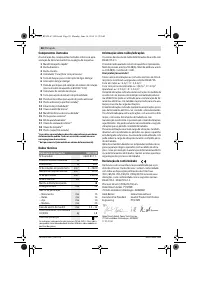
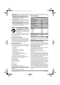
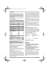
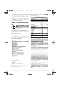
Noise/Vibration Information
Sound emission values determined according to
EN 60745-2-1.
Typically the A-weighted noise levels of the product are:
Sound pressure level 93 dB(A); Sound power level
104 dB(A). Uncertainty K = 3 dB.
Wear hearing protection!
Vibration total values a
h
(triax vector sum) and uncertainty K
determined according to EN 60745:
Drilling into metal: a
h
= 3 m/s
2
, K = 1.5 m/s
2
,
Impact drilling into concrete: a
h
= 26 m/s
2
, K = 3 m/s
2
,
Screwdriving without impact: a
h
< 2.5 m/s
2
, K = 1.5 m/s
2
.
The vibration level given in this information sheet has been
measured in accordance with a standardised test given in
EN 60745 and may be used to compare one tool with anoth-
er. It may be used for a preliminary assessment of exposure.
The declared vibration emission level represents the main ap-
plications of the tool. However if the tool is used for different
applications, with different accessories or insertion tools or is
poorly maintained, the vibration emission may differ. This
may significantly increase the exposure level over the total
working period.
An estimation of the level of exposure to vibration should also
take into account the times when the tool is switched off or
when it is running but not actually doing the job. This may signif-
icantly reduce the exposure level over the total working period.
Identify additional safety measures to protect the operator from
the effects of vibration such as: maintain the tool and the acces-
sories, keep the hands warm, organisation of work patterns.
Declaration of Conformity
We declare under our sole responsibility that the product de-
scribed under “Technical Data” is in conformity with all rele-
vant provisions of the directives 2011/65/EU, 2014/30/EU,
2006/42/EC including their amendments and complies with
the following standards: EN 60745-1, EN 60745-2-1.
Technical file (2006/42/EC) at:
Robert Bosch GmbH, PT/ETM9,
70764 Leinfelden-Echterdingen, GERMANY
Robert Bosch GmbH, Power Tools Division
70764 Leinfelden-Echterdingen, GERMANY
27.05.2014
Assembly
Before any work on the machine itself, pull the mains
plug.
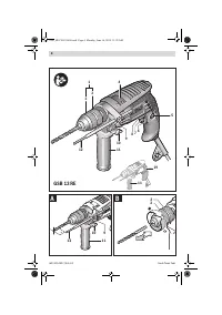
Auxiliary Handle (see figure A)
Operate your machine only with the auxiliary handle
11.
The auxiliary handle
11
can be set to any position for a secure
and low-fatigue working posture.
Turn the wing bolt for adjustment of the auxiliary handle
10
in
anticlockwise direction and set the auxiliary handle
11
to the
required position. Then tighten the wing bolt
10
again in
clockwise direction.
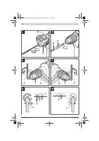
Adjusting the Drilling Depth (see figure A)
The required drilling depth
X
can be set with the depth stop
12
.
Press the button for the depth stop adjustment
9
and insert
the depth stop into the auxiliary handle
11
.
Pull out the depth stop until the distance between the tip of
the drill bit and the tip of the depth stop corresponds with the
desired drilling depth
X
.
Changing the Tool
Keyless Chuck (see figure B)
Hold the rear sleeve
3
of the keyless chuck
1
tight and turn the
front sleeve
2
in rotation direction
, until the tool can be in-
serted. Insert the tool.
Hold the rear sleeve
3
of the keyless chuck
1
tight and firmly
turn the front sleeve
2
in rotation direction
by hand until
the locking action is no longer heard. This automatically locks
the drill chuck.
The locking is released again to remove the tool when the
front sleeve
2
is turned in the opposite direction.
Key Type Drill Chuck (see figure C)
Wear protective gloves when changing the tool.
The
drill chuck can become very hot during longer work peri-
ods.
Open the key type drill chuck
14
by turning until the tool can
be inserted. Insert the tool.
Insert the chuck key
13
into the corresponding holes of the
key type drill chuck
14
and clamp the tool uniformly.
Screwdriver Tools (see figure D)
When working with screwdriver bits
16
, a universal bit holder
15
should always be used. Use only screwdriver bits that fit
the screw head.
For driving screws, always position the “Drilling/Impact Drill-
ing” selector switch
4
to the “Drilling” symbol.
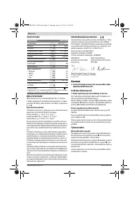
Chuck clamping range
mm
1.5 – 13
Weight according to
EPTA-Procedure 01/2003
kg
1.8
Protection class
/
II
Henk Becker
Executive Vice President
Engineering
Helmut Heinzelmann
Head of Product Certification
PT/ETM9
Impact Drill
GSB 13 RE
The values given are valid for a nominal voltage [U] of 230 V. For differ-
ent voltages and models for specific countries, these values can vary.
OBJ_BUCH-67-008.book Page 13 Monday, June 16, 2014 11:29 AM
Содержание
- 89 Указания по технике безопасности для дрелей
- 90 Описание продукта и услуг; Применение по назначению
- 91 Данные по шуму и вибрации; Заявление о соответствии; Сборка; Замена рабочего инструмента
- 92 Смена сверлильного патрона; Работа с инструментом; Включение электроинструмента
- 93 Техобслуживание и сервис; Техобслуживание и очистка; Утилизация
Характеристики

Остались вопросы?Не нашли свой ответ в руководстве или возникли другие проблемы? Задайте свой вопрос в форме ниже с подробным описанием вашей ситуации, чтобы другие люди и специалисты смогли дать на него ответ. Если вы знаете как решить проблему другого человека, пожалуйста, подскажите ему :)


