
Обогреватели Wing W150 AC 1-4-2801-0036 - инструкция пользователя по применению, эксплуатации и установке на русском языке. Мы надеемся, она поможет вам решить возникшие у вас вопросы при эксплуатации техники.
Если остались вопросы, задайте их в комментариях после инструкции.
"Загружаем инструкцию", означает, что нужно подождать пока файл загрузится и можно будет его читать онлайн. Некоторые инструкции очень большие и время их появления зависит от вашей скорости интернета.


31
EN
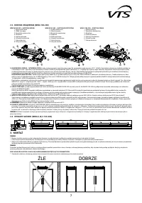
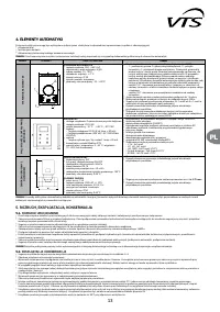
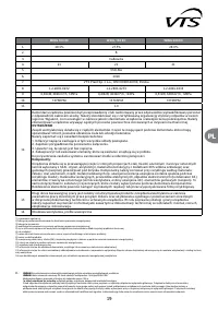
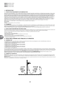
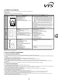
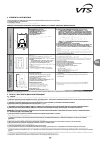
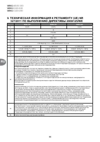
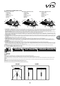
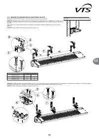
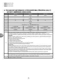
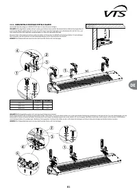
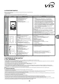
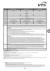
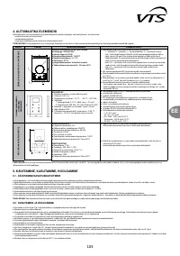
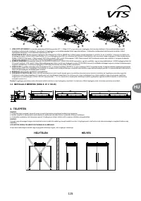
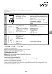
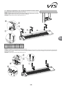
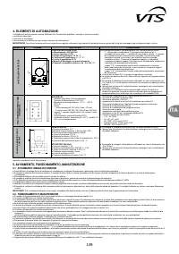
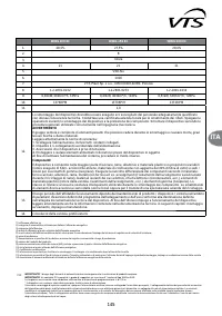
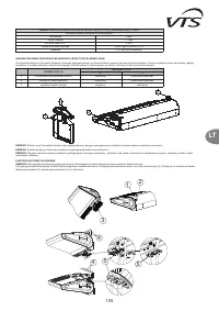
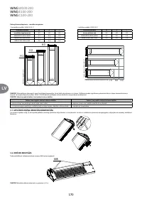
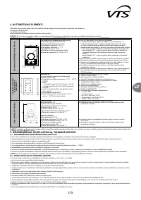
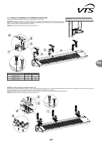
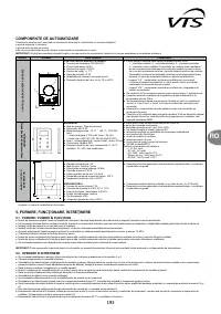
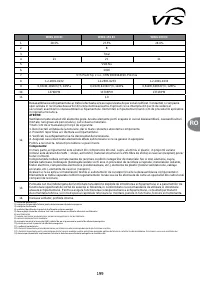
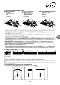
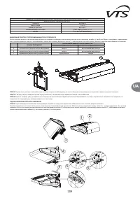
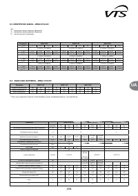
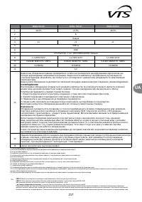
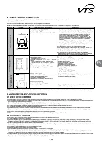
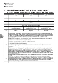
4. ELEMENTS OF AUTOMATICS.
(OHFWULFDOFRQQHFWLRQVFDQEHFDUULHGRXWRQO\E\TXDOL¿HGHOHFWULFLDQVDFFRUGLQJWRWKHELQGLQJUHJXODWLRQVRI
Ɣ
industrial safety;
Ɣ
sssembly instructions;
Ɣ
technical documentation for each individual element of automatics.
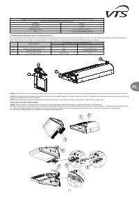
IMPORTANT!
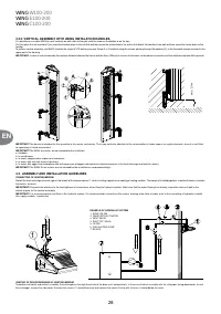
Study the original documentation delivered together with the elements of automatics, prior to the commencing of assembly and connecting of the system.
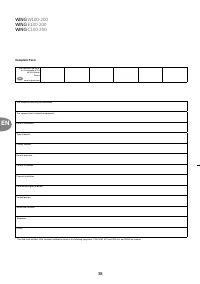
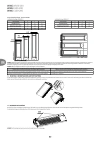
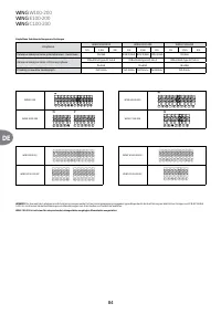
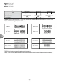
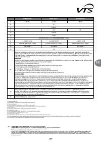
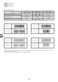
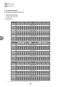
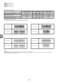
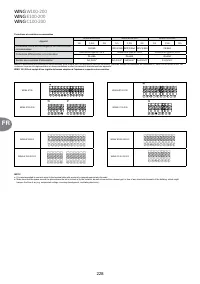
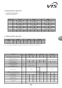
MODEL
DIAGRAM TECHNICAL
DATA
COMMENTS
W
A
LL-MOUNTED DX CONTROLLER
10
25
15
20
30
1
2
3
4
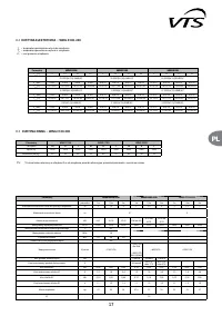
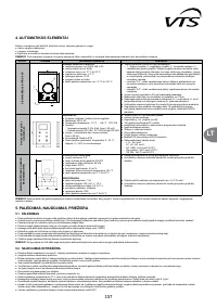
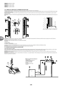
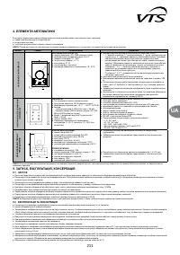
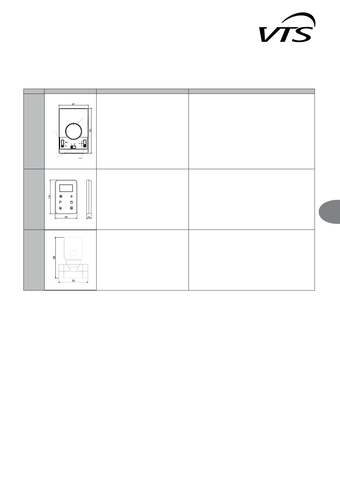
WALL-MOUNTED DX CONTROLLER
Ɣ
Supply voltage: 220-240 VAC
Ɣ
Permissible initial current: 6(3A)
Ɣ
Range of regulation: 10-30°C
Ɣ
Accuracy of regulation: +/- 1°C
Ɣ
Level of protection: IP 30
Ɣ
Assembly method: on plastered walls
Ɣ
Parameters of working environment: from -10 to +50°C
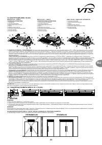
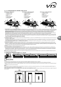
Ɣ 8VHGWRFRQWUROWKHRSHUDWLRQRIDOOW\SHVRI:,1*FXUWDLQV
– 1 - heating switch, 2 - main switch, 3 - thermostat crank, 4 - fan speed
switch. The heating switch for the water curtain controls the work of an
actuator installed on the valve, whereas for an electrical curtain - engages
electrical heaters. An in-built thermostat automatically disables heating or
the entire curtain, depending on the temperature set using the crank:
– jumper "2-5" - control of fan work and heating, depending on thermostat
setting; in this solution, the thermostat controls the operation of the entire
device
– jumper "4-5" - control of fan work, independently from thermostat setting
One wall-mounted DX controller can support the maximum of 1 curtain.
Ɣ 7KHPD[LPXPOHQJWKRIWKHFRQGXFWRUIURPWKHFXUWDLQWRWKHSURJUDPPLQJ
device, is 100 m.
Ɣ ,WLVUHFRPPHQGHGWRPDNHDFRQQHFWLRQXVLQJDFRQGXFWRURIWKHPLQVL]H[
1 mm2 or 6 x 1mm2 depend on the option of connection (see the schemes)
Ɣ 7KHGUDZLQJVZLWKWKHHOHPHQWVRIDXWRPDWLFVFRQWDLQRQO\YLVXDOLVDWLRQVRI
sample products.
Ɣ 7KHFRQWUROOHUGRHVQRWFRQVWLWXWHDQLQWHJUDOSDUWRIWKHFXUWDLQ,WLVDQ
optional device, which may be replaced with any programming device or
switch that conforms to the 60335 standard.
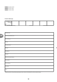
W
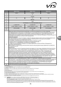
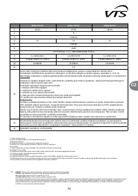
ALL-MOUNTED CONTROL P
ANEL
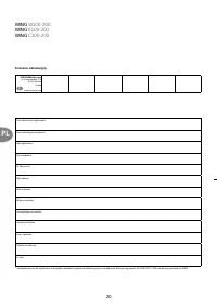
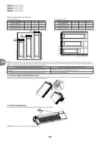
HMI-WING EC
HMI-WING EC
Ű
Device operation: Capacitive touch buttons
Ű
Power supply: 230 V AC
Ű
Temperature measurement: -10 °C ... +99 °C ; NTC10K
Ű
Outputs:
- 1 analog output 0-10V (8 bit, Imax = 20 mA)
- 2 relays outputs (250 VAC, AC1 500 VA dla 230 VAC)
Ű
Inputs: 1 digital input type “dry contact”, Imax = 20 mA
Ű
Communication: Modbus RTU
Ű
Parameters of working environment: temperature:
0 - 60 °C, humidity: 10 - 90%, without condensation
Ű
used for control all types of WING EC curtains
Ű
touch control panel
Ű
the main on / off switch (ON / OFF)
Ű
three-stage adjustable fan speed of the EC motor
Ű
built-in thermostat with possibility weekly programing
Ű
continuous mode
Ű
function of heating and ventilation
Ű
REVáXJDF]XMQLNDGU]ZLRZHJR
Ű
two-stage adjustable of heating power
Ű
RS 485 with ModbusRTU
Ű
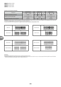
Suggested cross sections of electrical cables::
- L, N : 2x1 mm2
- H1, H2 : 2x1 mm2
- AO, GND : 2x0,5 mm2 LIYCY
- Door sensor : 2x0,5 mm2 LIYCY
- RS 485 : 3x0,75 mm2 LIYCY
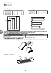
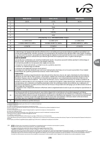
TWO-W
A
Y
V
A
L
VE WITH
ACTUA
T
O
R
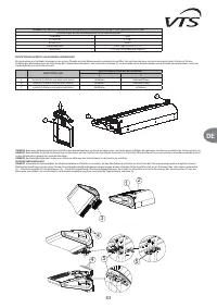
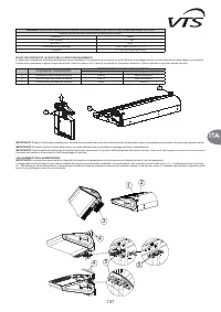
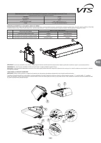
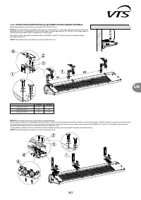
TWO-WAY VALVE
Ɣ
Terminal diameter: 3/4”
Ɣ
Mode of operation: two-way ON/OFF
Ɣ
Maximum differential pressure: 90kPa
Ɣ
Pressure class: PN 16
Ɣ .YVÀRZUDWLRPK
Ɣ
Maximum temperature of heating medium: 105°C
Ɣ
Parameters of working environment: from 0 to 60°C
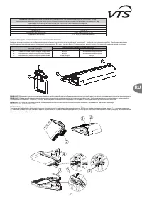
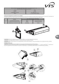
VALVE ACTUATOR
Ɣ
Power consumption: 7 VA
Ɣ
Supply voltage: 230VAC +/-10%
Ɣ
Closing/opening time: 4-5/9-11 s
Ɣ
Position without power: closed
Ɣ
Level of protection: IP54
Ɣ
Parameters of working environment: from 0 to 60°C
Ɣ ,WLVUHFRPPHQGHGWRLQVWDOODWZRZD\YDOYHRQWKHUHWXUQSLSHOLQH
Ɣ 7KHGUDZLQJVZLWKWKHHOHPHQWVRIDXWRPDWLFVFRQWDLQRQO\YLVXDOLVDWLRQVRI
sample products.
Ɣ ,WLVUHFRPPHQGHGWRFRQQHFWWKHVXSSO\XVLQJDFRQGXFWRURIWKHPLQVL]H
2x0.75 mm
2
.
Ɣ 7KHGUDZLQJVZLWKWKHHOHPHQWVRIDXWRPDWLFVFRQWDLQRQO\YLVXDOLVDWLRQVRI
sample products.
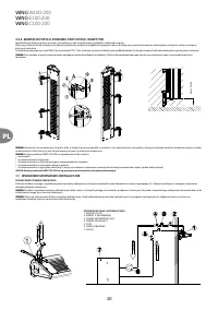
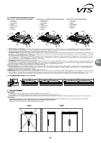
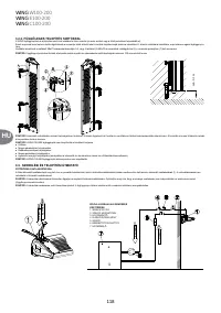
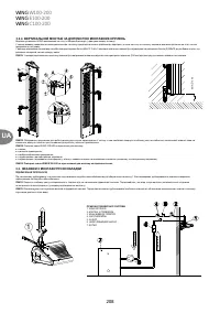
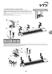
IMPORTANT!
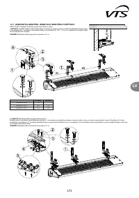
If required, the conductors that belong to additional elements of control automatics (thermostat, door switch, wall-mounted controller) should be installed in separate cable
channels, out-of-parallel to the supply conductors.
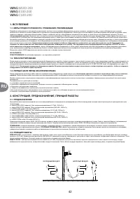
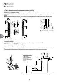
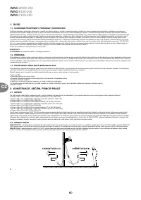
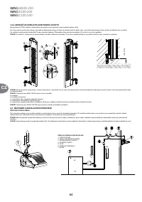
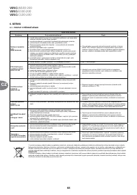
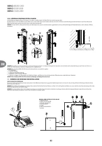
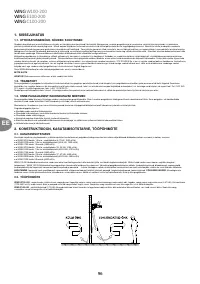
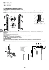
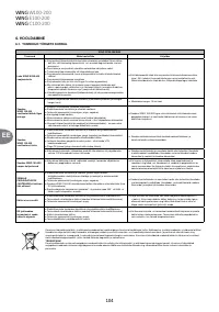
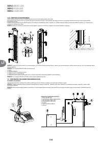
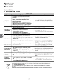
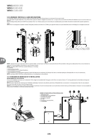
5. START-UP, OPERATION, MAINTENANCE
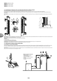
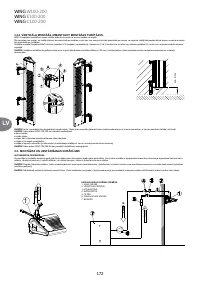
5.1. START-UP/PUTTING INTO OPERATION
Ɣ
Prior to the commencing of any installation or maintenance work, disconnect power supply and secure it against unintentional reactivation.
Ɣ ,WLVUHFRPPHQGHGWRXVH¿OWHUVLQWKHK\GUDXOLFV\VWHP,WLVUHFRPPHQGHGWRFOHDQULQVHWKHV\VWHPGUDLQLQJDIHZOLWUHVRIZDWHUSULRUWRWKHFRQQHFWLQJRIK\GUDXOLFFRQGXLWVWKHVXSSO\FRQGXLWV
in particular).
Ɣ
It is advised to use vent valves in the highest point of the system.
Ɣ
It is recommended to install shut-off valves directly after the device, should the disassembly of the device be necessary.
Ɣ
All protective equipment is to be installed before the pressure increases, according to maximum the permissible pressure rating of 1.6MPa.
Ɣ
Hydraulic connection should be free of any stresses and loads.
Ɣ &KHFNWKHFRUUHFWQHVVRIK\GUDXOLFFRQQHFWLRQVOHDNWLJKWQHVVRIWKHYHQWFROOHFWLQJSLSHVFRUUHFWQHVVRI¿WWLQJVLQVWDOODWLRQSULRUWRWKHLQLWLDOVWDUWXSRIWKHGHYLFH
Ɣ
It is recommended to check the correctness of electrical connections (of automatics, power supply), prior to the initial start-up of the device. It is advised to use an additional, external residual-
current protection.
IMPORTANT!
All connections should be carried out, according to this technical documentation and the documentation delivered with automation equipment.
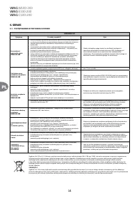
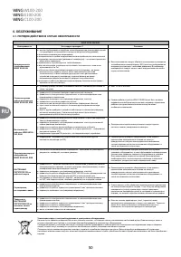
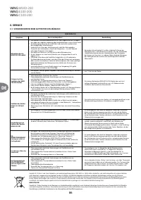
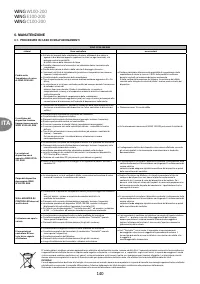
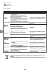
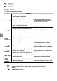
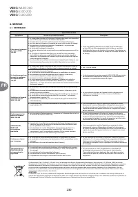
5.2. OPERATION AND MAINTENANCE
Ɣ
It is advised to carefully analyse all the operational and assembly guidelines listed in chapter 3 and 4.
Ɣ
The casing of the device does not require maintenance.
Ɣ
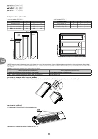
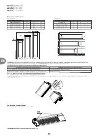
The heat exchanger should be cleaned on a regular basis from dust and fat deposit. It is especially recommended to clean the exchanger before the heating season with the use of compressed air
from the air intake side (after removing the inlet grid). You should pay special attention to the exchanger's lamellae which are very delicate.
Ɣ
Should the lamellas be deformed (bent), straighten them with a special tool.
Ɣ
The fan's motor does not require any exploitation service, the only service activities that may be necessary concern cleaning the air intakes from dust and fat deposit.
Ɣ
Disconnect phase voltage, if the device is shut down for longer periods of time.
Ɣ
The heat exchanger does not have any anti-freezing protections.
Ɣ
It is recommended to provide a periodical purging of the heat exchanger, preferably using compressed air.
Ɣ
Should the temperature in the room drop below 0°C, with a simultaneous drop of the heating medium temperature, there is a risk that the heat exchanger might freeze (crack).
Ɣ
The level of air pollutants should meet the criteria allowable concentrations of pollutants in indoor air, for non-industrial areas, the level of dust concentration up to 0.3 g / m³.
Ɣ
It is forbidden to use device for the duration of the construction works except for the start-up of the system.
Ɣ 7KHHTXLSPHQWPXVWEHRSHUDWHGLQURRPVXVHGWKURXJKRXWWKH\HDUDQGLQZKLFKWKHUHLVQRFRQGHQVDWLRQODUJHÀXFWXDWLRQVLQWHPSHUDWXUHHVSHFLDOO\EHORZWKHGHZSRLQWRIWKHPRLVWXUH
content). The device should not be exposed to direct UV rays.
Ɣ
The device should be operated at the supply water temperature up to 90 °C with working fan.


