Материнские платы GIGABYTE GA 8I865P - инструкция пользователя по применению, эксплуатации и установке на русском языке. Мы надеемся, она поможет вам решить возникшие у вас вопросы при эксплуатации техники.
Если остались вопросы, задайте их в комментариях после инструкции.
"Загружаем инструкцию", означает, что нужно подождать пока файл загрузится и можно будет его читать онлайн. Некоторые инструкции очень большие и время их появления зависит от вашей скорости интернета.


- 24 -
GA-8I865P(-G) M otherboard
English
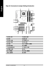
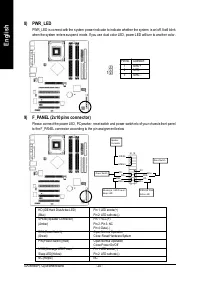
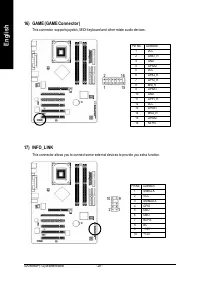
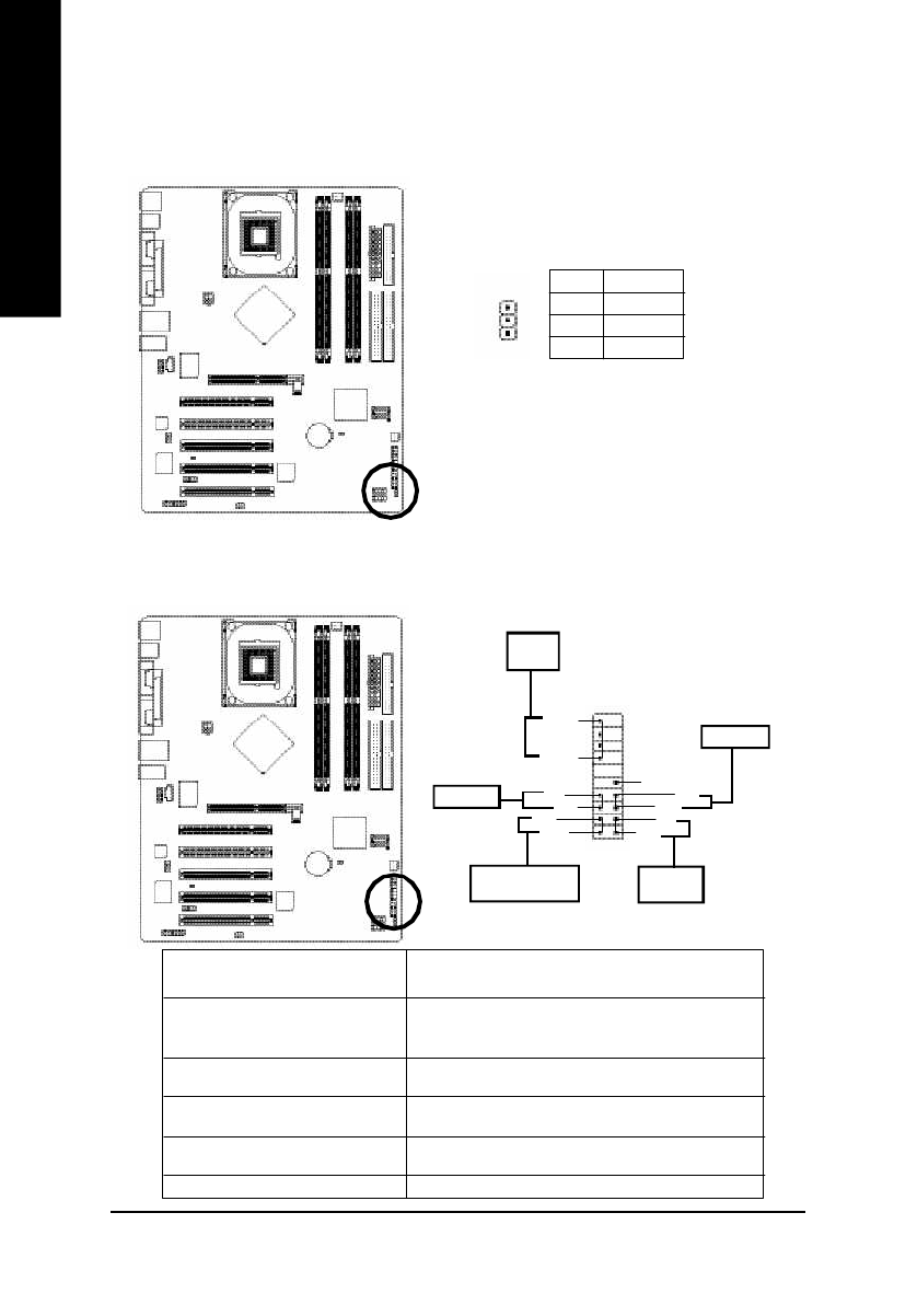
8) PWR_LED
PWR_LED is connect with the system power indicator to indicate whether the system is on/off. It will blink
when the system enters suspend mode. If you use dual color LED, power LED will turn to another color.
Pin No. Definition
1
MPD+
2
MPD-
3
MPD-
1
9) F_PANEL (2x10 pins connector)
Please connect the power LED, PC peaker, reset switch and power switch etc of your chassis front panel
to the F_PANEL connector according to the pin assignm ent below.
HD (IDE Hard Disk Ac tive LED)
Pin 1: LED anode(+)
(Blue)
Pin 2: LED c athode(-)
SPEAK (Speaker Connec tor)
Pin 1: VCC(+)
(Amber)
Pin 2- Pin 3: NC
Pin 4: Data(-)
RES (Reset Switc h)
Open: Normal Operation
(Green)
Close: Reset Hardware System
PW (Power Switc h) (Red)
Open: Normal Operation
Close: Power On/Off
MSG (Message LED/Power/
Pin 1: LED anode(+)
Sleep LED)(Yellow)
Pin 2: LED c athode(-)
NC (Purple)
NC
SPEAK-
SPEAK+
20
Speaker
Connector
19
ID E H ard Di sk
Ac tiv e L ED
Res et Swi tch
2
Pow er Swi tch
MSG +
MSG -
Me s s a g e LED / Po w e r /
Sleep LED
PW -
PW +
1
HD +
HD-
R ES+
RES-
N C


