
Водонагреватели Gorenje GBK120RNB6 - инструкция пользователя по применению, эксплуатации и установке на русском языке. Мы надеемся, она поможет вам решить возникшие у вас вопросы при эксплуатации техники.
Если остались вопросы, задайте их в комментариях после инструкции.
"Загружаем инструкцию", означает, что нужно подождать пока файл загрузится и можно будет его читать онлайн. Некоторые инструкции очень большие и время их появления зависит от вашей скорости интернета.


17
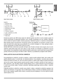
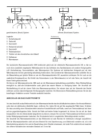
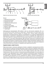
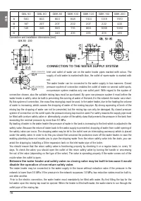
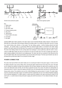
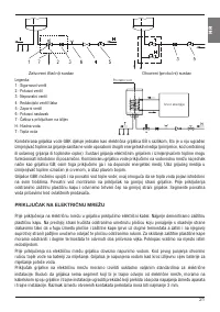
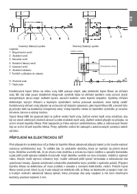
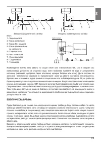
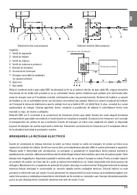
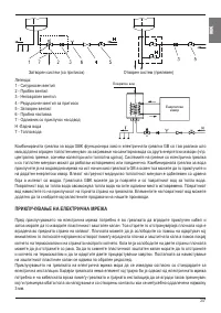
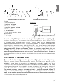
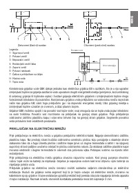
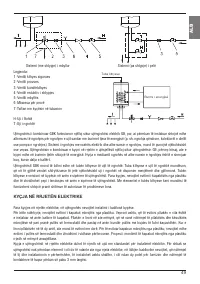
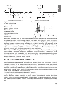
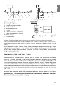
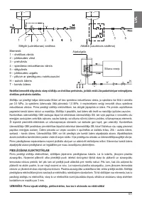
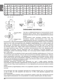
Closed-circuit (pressure) system
Open-circuit (gravity) system
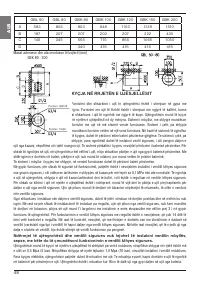
Combined GBK water heater operates in the same manner as the electrical GB water heater however, it has also been
fitted with the cooling water heat exchanger allowing the sanitary water to be heated by alternative sources of energy
(e.g. central heating, solar collector or heat pump). The two heating systems - electrical heating element and heat
exchanger - can operate singly or concurrently. While the combined water heater is connected to the water supply
system in the same manner as the GB model, the connection to the additional energy source has to be made as well.
The inlet of the heating medium into the cooling water heat exchanger is colour-coded blue, while the outlet is colour-
coded red. GBK water heaters can also be connected to the return hot water pipe. The return hot water pipe makes hot
water instantly available at all points of use simultaneously. The return pipe can be connected to the inlet point at the
top of the water heater after removing the plastic cap and unscrewing the stopper. The return pipe elements can also be
purchased at any authorised dealer of our products at a later stage.
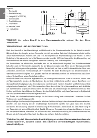
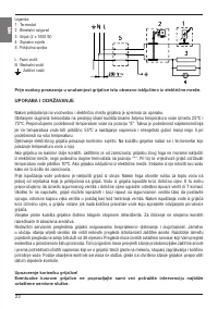
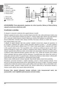
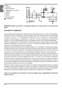
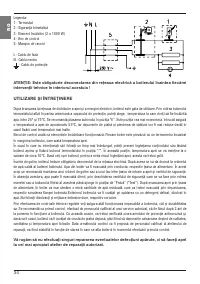
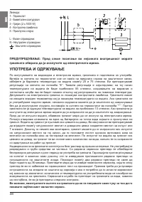
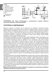
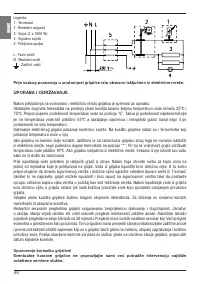
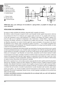
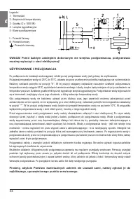
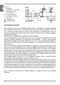
POWER CONNECTION
The power lead must be fitted to the water heater prior to connecting the heater to the power supply. In order to do this
the plastic protective cover must be taken off by removing the plate inserted into the front side of the cover. The plate
can be released by carefully inserting a flat screwdriver into the fissure between the plate and the protective cap, first
next to the thermostat knob and then into the fissure opposite the knob. Once loose, the plate can subsequently be
removed by hand. In order to remove the plastic protective cover, the thermostat knob must also be removed and both
fixing screws undone. The protective cover can be re-fitted following the same procedure in reverse. The water heater
must be connected to the power supply in accordance with the requirements set out in the relevant standards applying
to the electrical installations. For safety reasons, a switch should be installed on the lead connecting the heater to the
power grid, i.e. a switch disconnecting both power supply poles with the minimum of 3 mm distance between the open
contacts.
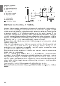
Key:
1 - Safety valve
2 - Test valve
3 - Non-return valve
4 - Pressure-reducing valve
5 - Stop valve
6 - Testing piece
7 - Funnel outlet to the drain
H - Cold water
T - Hot water
Return pipe
Energy source
GB
Содержание
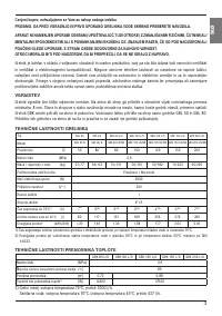
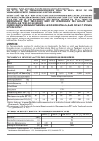
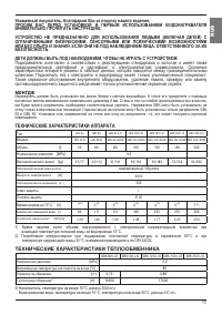
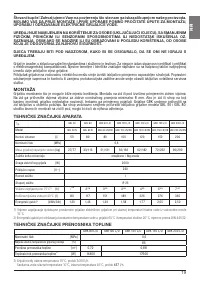
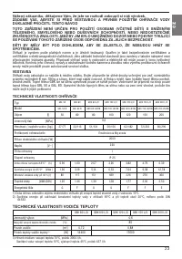
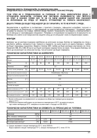
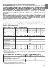
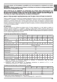
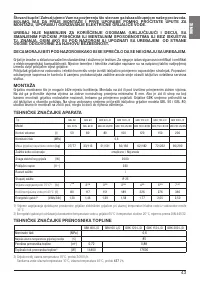
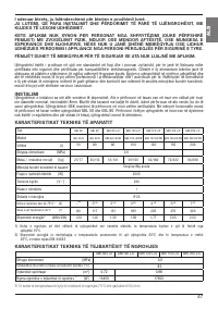
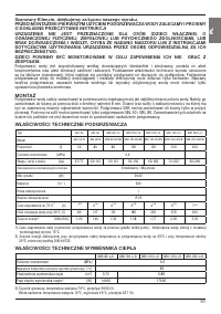
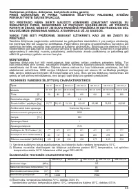
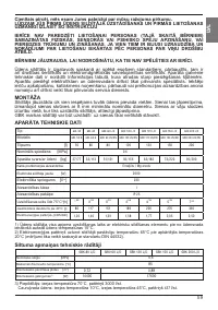
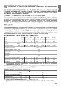
- 11 Уважаемый покупатель, благодарим Вас за покупку нашего изделия.; монтдж; ТЕХНИЧЕСКИЕ ХАРАКТЕРИСТИКИ АППАРАТА; входящей температуре холодной воды из водопровода 15°C.; ТЕХНИЧЕСКИЕ ХАРАКТЕРИСТИКИ ТЕПЛООБМЕННИКА; US
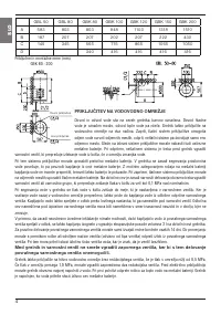
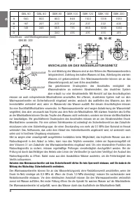
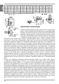
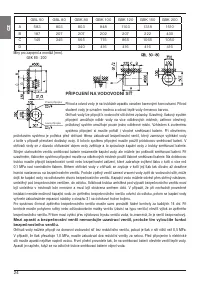
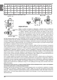
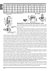
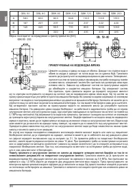
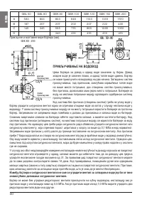
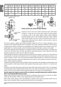
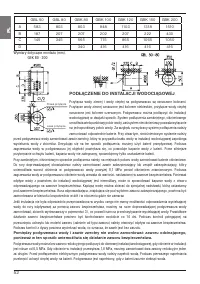
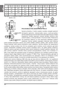
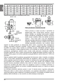
- 12 Соединительные и монтажные размеры водонагревателя [мм]; ПОДКЛЮЧЕНИЕ K ВОДОПРОВОДУ; от выбранной системы подключения. B открытой проточной системе
- 13 ПОДKЛЮЧЕНИЕ K ЭЛЕКТРОСЕТИ
- 14 ИСПОЛЬЗОВАНИЕ И УХОД


