
Шуруповерты VERTO 50G852 - инструкция пользователя по применению, эксплуатации и установке на русском языке. Мы надеемся, она поможет вам решить возникшие у вас вопросы при эксплуатации техники.
Если остались вопросы, задайте их в комментариях после инструкции.
"Загружаем инструкцию", означает, что нужно подождать пока файл загрузится и можно будет его читать онлайн. Некоторые инструкции очень большие и время их появления зависит от вашей скорости интернета.


8
TRANSLATION OF THE ORIGINAL INSTRUCTIONS
IMPACT DRILL
50G852
CAUTION: BEFORE USING THE POWER TOOL READ THIS MANUAL
CAREFULLY AND KEEP IT FOR FUTURE REFERENCE.
DETAILED SAFETY REGULATIONS
• Use ear protectors when operating impact drill.
Noise hazards may
cause hearing loss.
• Use additional handles supplied with the tool.
Loss of control may
cause operator personal injury.
Description of improper use
Do not throw the tool, do not overload, do not immerse in water or other
fluids, do not use for mixing adhesive or cement mortars, do not hang,
carry, pull or unplug the power tool by pulling the cord. Avoid using long
extension cords.
Accessories that you can use
Wood, metal and masonry drills, grinding discs and wire brushes (wear
safety goggles when using grinding discs and wire brushes).
CAUTION! This device is designed to operate indoors.
The design is assumed to be safe, protection measures and
additional safety systems are used, nevertheless there is always a
small risk of operational injuries.
CONSTRUCTION AND USE
Impact drills are hand operated power tools with insulation class II. Tools
are driven by single-phase commutator motors with rotational speed
reduced with gear transmission. This type of power tools is widely used
for making holes in wood, wood-like materials, metals, ceramics and
plastics (rotation only), and concrete, bricks and alike (with impact).
Range of use covers repair and building works, woodworking and any
work from the scope of individual, amateur activities (tinkering).
Use the power tool according to the manufacturer’s instructions only.
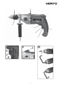
DESCRIPTION OF DRAWING PAGES
Below enumeration refers to the device elements depicted on the
drawing pages of this manual.
1.
Drill chuck
2.
Operation mode switch
3.
Switch lock button
4.
Direction selector switch
5.
Wheel for rotational speed control
6.
Switch
7.
Additional handle
8.
Depth gauge rod
9.
Gear switch
* Slight differences may appear between the product and drawing
MEANING OF SYMBOLS
CAUTION
WARNING
ASSEMBLY/SETTINGS
INFORMATION
EQUIPMENT AND ACCESSORIES
1. Key - handwheel
2
. Additional
handle
3
. Depth gauge rod
PREPARATION FOR OPERATION
INSTALLATION OF ADDITIONAL HANDLE
Due to personal safety issues it is recommended to always use the
additional handle (7). Possibility to rotate the additional handle
before it is clamped on the drill body allows choosing the position
most comfortable for specific working conditions.
GB
Disconnect the power tool from power supply.
•
Loosen the wheel lock that locks collar of the locking handle (
7
) by
turning it counter-clockwise.
•
Slide the handle collar over cylindrical part of the drill body.
•
Turn for the most comfortable position.
•
Turn the wheel lock clockwise tightly to clamp the handle.
DEPTH GAUGE INSTALLATION
Depth gauge
(8)
serves to limit the depth of drill penetration of material
•
Loosen the wheel lock, which blocks collar of the additional handle
(
7
).
•
Slide depth gauge rod (
8
) into the hole in the additional handle collar.
•
Set desired drill depth.
•
Fix by tightening the wheel lock.
INSTALLATION OF WORKING TOOLS
Disconnect the power tool from power supply.
•
Insert key into one of the holes on the side wall of the drill chuck (
1
).
•
Open jaws to desired dimension.
•
Insert cylindrical drill shank into the chuck, push it to the limit.
•
Tighten jaws on drill shank with the key (insert it into three holes on
the chuck side wall).
Remember to always remove the key from the chuck after you finish
drill installation or removal.
OPERATION / SETTINGS
SWITCHING ON / SWITCHING OFF
The mains voltage must match the voltage on the rating plate of
the drill.
Switching on
– press the switch button (
6
) and hold in this position.
Switching off
– release pressure on the switch (
6
).
Locking the switch (continuous operation)
Switching on:
•
Press the switch button (
6
) and hold in this position.
•
Press the switch lock button (
3
)
(fig. A)
.
•
Release pressure on the switch (
6
).
Switching off:
•
Press and release the switch (
6
).
Range of rotational speed of the spindle is controlled with pressure
on the switch button.
WHEEL FOR SPINDLE ROTATIONAL SPEED CONTROL
Drill allows for operation with different spindle speeds. It can be
controlled with the wheel (
5
)
(fig. A)
. For each setting of the wheel for
speed control, the speed can be adjusted continuously by increasing or
decreasing pressure on the switch button (
6
).
•
Increase the speed by turning the wheel (
5
) clockwise.
•
Reduce the speed by turning the wheel (
5
) counter-clockwise.
Choose appropriate rotational speed when the drill operates with no
load, with pressed switch lock button. Speed that is set in this way may
decrease under load.
CHANGE OF GEAR
Drill is equipped with gear switch (
9
), which broadens the range of
rotational speed (
fig. C
).
Gear I
: lower range of rotational speeds – for large diameter holes or for
works with hard material.
Gear II
: higher range of rotational speeds – for small diameter holes or
for works with soft material.
Set the gear switch (
9
) in appropriate position depending on the
processed material. Turn the spindle slightly if the switch cannot be
moved.
Never change the switch position under operation of the drill. It
may damage the power tool.
LEFT – RIGHT DIRECTION OF ROTATION
Choose direction of spindle rotation with the selector switch (
4
) (
fig. A
).
Right rotation –
move the switch (
4
) to the extreme left position.
Left rotation –
move the switch (
4
) to the extreme right position.
* The possibility is reserved that in certain cases position of the switch relating to
rotation direction may be different than specified. Please refer to graphic signs placed
on the switch or tool body.
Do not change direction of rotation when the spindle of the drill is
rotating. Check if the position of the selector switch is correct before
starting the tool.

