
Шуруповерты Verto 50G187 - инструкция пользователя по применению, эксплуатации и установке на русском языке. Мы надеемся, она поможет вам решить возникшие у вас вопросы при эксплуатации техники.
Если остались вопросы, задайте их в комментариях после инструкции.
"Загружаем инструкцию", означает, что нужно подождать пока файл загрузится и можно будет его читать онлайн. Некоторые инструкции очень большие и время их появления зависит от вашей скорости интернета.


12
•
When drilling, choose setting marked with the drill
symbol. The torque is the greatest with this setting.
•
Knowledge how to choose appropriate torque setting
comes with practice.
Setting the torque adjustment ring in the drilling
position deactivates the overload clutch.
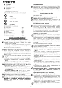
WO R K I N G TO O L I N S TA L L AT I O N
•
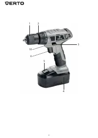
Set the direction selector switch (
3
) in the middle
position.
•
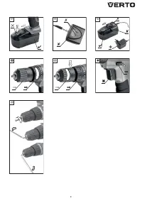
Hold the rear ring of the quick release chuck (
1
) and
turning the front ring clockwise to set required jaw
spread and inser t appropriate drill or driver bit (
fig. E
).
•
Hold the rear ring and turn the front ring of the quick
release chuck (
1
) counter clockwise, firmly tighten.
Deinstallation of the tool is similar to installation, only the
sequence of actions is reversed.
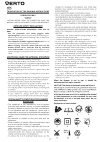
Make sure the tool position is correct when installing
drill or driver bit in the quick release chuck. Use
additional magnetic adapter as an extension when
using shor t driver bits.
RIGHT-LEFT DIREC TION OF ROTATION
Choose direction of spindle rotation with the direction
selector switch (
3
) (
fig. F
).
Clockwise rotation
– set the direction selector switch (
3
)
to the extreme left position.
Counter-clockwise rotation
– set the direction selector
switch (
3
) to the extreme right position.
* In cer tain cases position of the switch related to rotation may be different than
specified. Please refer to graphic signs located on the switch or tool body.
Safe position of the direction selector switch (
3
) is in the
middle, it prevents accidental star ting of the power tool.
•
Drill cannot be star ted, when the switch is in this
position.
•
Use this position of the switch to change drills or bits.
•
Before star ting the tool make sure the position of the
direction selector switch (
3
) is correct.
Do not change direction of rotation when the drill
spindle is rotating.
Long lasting drilling at low rotational speed of the
spindle may cause motor overheating. Provide regular
breaks during operation or let the tool operate at
maximum speed with no load for approximately 3
minutes.
OPERATION AND MAINTENANCE
M A I N T E N A N C E A N D S TO R AG E
•
Cleaning the device after each use is recommended.
•
Do not use water or any other liquid for cleaning.
•
Clean the drill with a dr y cloth or blow with compressed
air at low pressure.
•
Do not use any cleaning agents or solvents, they may
damage plastic par ts.
•
Clean ventilation holes in the motor casing regularly to
prevent device overheating.
•
In case of excessive commutator sparking, have the
technical condition of carbon brushes of the motor
checked by a qualified person.
•
Store the drill in a dr y place, beyond reach of children.
Q U I C K R E L E A S E C H U C K R E P L AC E M E N T
Quick release chuck is screwed onto spindle of the drill and
additionally secured with a screw.
•
Set the direction selector switch (
3
) in the middle
position.
•
Open jaws of quick release chuck (
1
) and unscrew the
fixing screw (left-hand thread) (
fig. G
).
•
Install hexagonal key in the quick release chuck and tap
the other end of the key.
•
Unscrew the quick release chuck.
•
Installation of the quick release chuck is similar to
deinstallation, only the sequence of actions is reversed.
All defects should be repaired by ser vice workshop
authorized by the manufacturer.
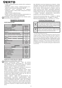
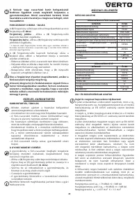
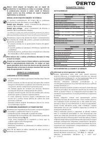
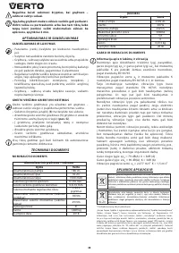
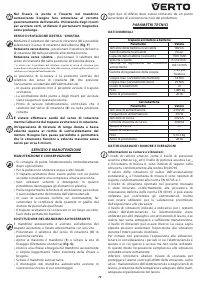
TECHNICAL PARAMETERS
R AT E D PA R A M E T E R S
Cordless drill
Parameter
Value
Battery voltage
18V DC
Battery type
Ni-Zn
Battery capacity
1500 mAh
Range of idle rotational speed
0-550 min
-1
Range of quick release chuck
0,8-10 mm
Torque control range
1–20 plus drilling
Max. torque (soft drive)
18 Nm
Max. torque (hard drive)
29 Nm
Protection class
III
Weight
1,489 kg
Year of production
2018
Charger
Parameter
Value
Supply voltage
230V AC
Power supply frequency
50 Hz
Charging voltage
24V DC
Max. charging current
300mA
Battery charging time
5 h
Protection class
II
Weight
0,073 kg
Year of production
2018
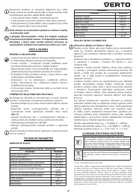
N O I S E A N D V I B R AT I O N DATA
Information regarding noise and vibration
The following levels of emitted noise, such as emitted
acoustic pressure Lp
A
and acoustic power level Lw
A
and
measurement uncer tainty K have been given in the
instruction manual as defined in the EN 60745 standard.
The following vibration value (acceleration value) a
h
and
measurement uncer tainty K have been determined as
defined in the EN 60745-2-1 standard.
The vibration level provided in this instruction manual
have been determined according to the measurement
procedure as defined in the EN 60745 standard and can be
used for comparison of power tools. This can be used for
preliminar y assessment of exposure to vibrations.
The provided vibration level is representative for main
applications of the power tool. If the power tool is used
for other applications or with other working tools, and if it
is not sufficiently maintained, the vibration level may var y.
The aforementioned reasons may increase the exposure to
vibrations during the entire operating period.
In order to precisely estimate the exposure to vibrations,
periods should be accounted for, in which the power
tool is switched off, or when it is switched on, but not
operated. Thus, the total exposure to vibration may prove
considerably lower.
Содержание
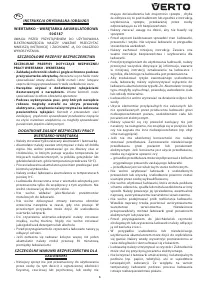
- 17 Д Р Е Л Ь - Ш У РУ П О В Е Р Т А К К УМУЛ Я ТО Р Н А Я; • Во время работы с дрелью-шуруповертом; частицы могут вызвать повреждение г лаз.; • Работайте дополнительными рукоятками,; При прикосновении рабочего инструмента
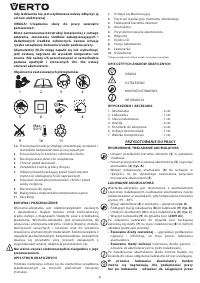
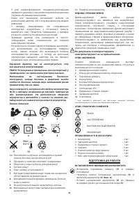
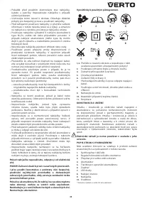
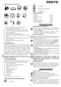
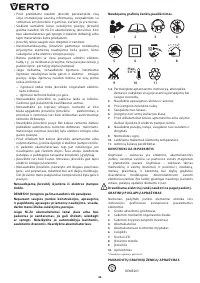
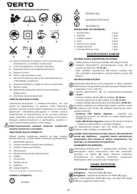
- 18 Не предпринимайте попыток самостоятельного; Расшифровка пиктограмм.; Пользуйтесь защитными очками и наушниками.
- 19 ПОДГОТОВКА К РАБОТЕ
- 20 ТЕХНИЧЕСКОЕ ОБС ЛУ ЖИВАНИЕ
- 21 ИНФОРМАЦИЯ О ДАТЕ ИЗГОТОВЛЕНИЯ

