
Шуруповерты Verto 50G187 - инструкция пользователя по применению, эксплуатации и установке на русском языке. Мы надеемся, она поможет вам решить возникшие у вас вопросы при эксплуатации техники.
Если остались вопросы, задайте их в комментариях после инструкции.
"Загружаем инструкцию", означает, что нужно подождать пока файл загрузится и можно будет его читать онлайн. Некоторые инструкции очень большие и время их появления зависит от вашей скорости интернета.


11
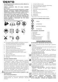
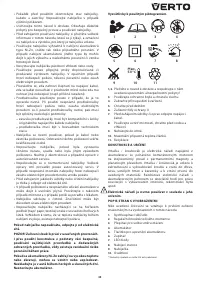
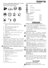
1,2.
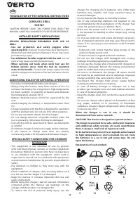
Read the instruction manual, obser ve warnings and
safety conditions therein.
3.
Use protective goggles and hearing protectors.
4.
Keep the tool away from children.
5.
Protect against rain.
6.
Device with class II insulation.
7.
Disconnect the power cord before star ting
maintenance or operation.
8.
Use indoors, protect from water and moisture.
9.
Do not throw into fire.
10.
Maximum permissible cell temperature.
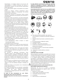
11.
Recycling
CONSTRUC TION AND USE
Drill is a batter y powered tool. Drive consists of a DC
commutator motor with permanent magnets and
planetar y gear. Drill is designed for screwing in and out
screws and bolts in wood, metal, plastics and ceramics,
and for drilling holes in those materials. Cordless, batter y-
powered power tools are especially useful for works in
interior furnishing, adaptation of premises etc.
Use the power tool according to the manufacturer’s
instructions only.
D E S C R I P T I O N O F D R AW I N G PAG E S
Below enumeration refers to the device elements depicted
on the drawing pages of this manual.
1.
Quick-release chuck
2.
Torque adjustment ring
3.
Direction selector switch
4.
Batter y
5.
Batter y lock button
6.
Switch
7.
LED diodes
8.
Charging station
9.
Charger
10.
Lighting
* Differences may appear between the product and drawing.
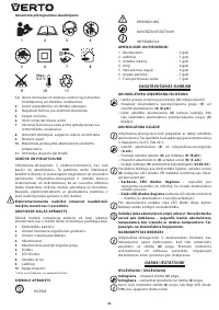
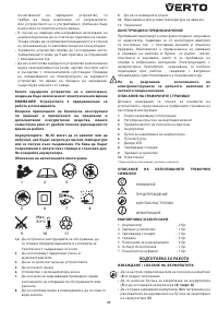
M E A N I N G O F S YM B O L S
CAUTION
WARNING
ASSEMBLY / SET TINGS
INFORMATION
E Q U I PM E N T A N D ACC E S S O R I E S
1. Batter y
- 2 pcs
2. Charger
- 1 pce
3. Charging station
- 1 pce
4. Drills
- 6 pcs
5. Driver bits
- 6 pcs
6. Bit holder
- 1 pce
7. Carr ying case
- 1 pce
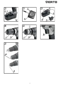
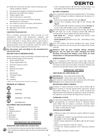
PREPARATION FOR OPERATION
REMOVING AND INSERTING THE BAT TERY
•
Set the direction selector switch (
3
) in middle position.
•
Push batter y lock button (
5
) and slide out the batter y (
4
)
(
fig. A
).
•
Inser t charged batter y (
4
) into the handle holder, you
should hear when the batter y lock button (
5
) snaps.
BAT TERY CHARGING
Drill is supplied with par tially charged batter y. The batter y
should be charged in ambient temperature between 4°C
and 40°C.
•
Remove the batter y (
4
) from the drill (
fig. A
).
•
Connect the charging station (
8
) to the charger (
9
)
(
fig. B
).
•
Put the batter y (
4
) inside the charging station (
8
) (
fig. C
).
•
Connect the charger (
9
) to mains socket (
230V AC
).
Once the charger is connected to mains socket, LED diodes
(
7
) will light up on the charging station (
8
), different
configurations are possible (see description below).
• Red diode lit
– voltage supplied and informs that
charging is in progress.
• Green diode lit
(red diode turns off ) – the batter y is fully
charged.
Once the batter y has been charged, the green diode
stays on until you will disconnect the charger from mains
network.
Batteries heat up very strongly during charging
process. Do not work just after charging has been
finished, wait until the battery cools down to room
temperature. It will prevent battery damage.
S P I N D L E B R A K E
Drill is equipped with electronic brake that stops the
spindle immediately after the switch button (
6
) is released.
The brake ensures precision when screwing or drilling and
prevents free spindle rotation after switching off.
OPERATION / SET TINGS
S W I TC H I N G O N / S W I TC H I N G O F F
Switching on
– press the switch button (
6
).
Switching off
– release the switch button (
6
).
Each time the switch button (
6
) is pressed, the LED diode
(
10
) lights up to illuminate the workplace.
ROTATIONAL SPEED CONTROL
Increase or reduce pressure on the switch button (
6
) to
adjust drilling or driving speed while operating. Speed
adjustment allows for a soft star t, which prevents dill
slipping when drilling holes in gypsum or glaze, and allows
for operation control when driving screws in and out.
OV E R LOA D C LU TC H
Set the torque adjustment ring (
2
) in appropriate position
to permanently set overload clutch to defined torque
value. When the set torque is reached, overload clutch
disconnects automatically. It prevents from driving screws
too deep or damaging the drill.
TO RQUE ADJUSTMENT
•
Different screws and materials require different torque
to be applied.
•
The bigger the number corresponding to given position,
the bigger is the torque (
fig. D
).
•
Set the torque adjustment ring (
2
) to appropriate torque
value.
•
Always star t operation with low torque.
•
Increase the torque gradually until obtaining desired
results.
•
Use higher settings to undo screws.
Содержание
- 17 Д Р Е Л Ь - Ш У РУ П О В Е Р Т А К К УМУЛ Я ТО Р Н А Я; • Во время работы с дрелью-шуруповертом; частицы могут вызвать повреждение г лаз.; • Работайте дополнительными рукоятками,; При прикосновении рабочего инструмента
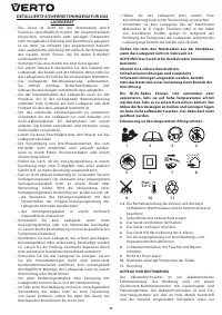
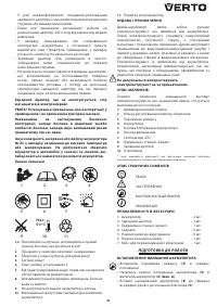
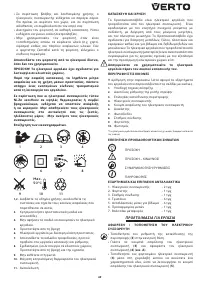
- 18 Не предпринимайте попыток самостоятельного; Расшифровка пиктограмм.; Пользуйтесь защитными очками и наушниками.
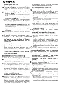
- 19 ПОДГОТОВКА К РАБОТЕ
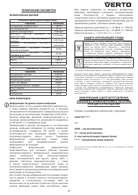
- 20 ТЕХНИЧЕСКОЕ ОБС ЛУ ЖИВАНИЕ
- 21 ИНФОРМАЦИЯ О ДАТЕ ИЗГОТОВЛЕНИЯ

