Материнские платы GIGABYTE G1 Guerrilla rev 1 0 - инструкция пользователя по применению, эксплуатации и установке на русском языке. Мы надеемся, она поможет вам решить возникшие у вас вопросы при эксплуатации техники.
Если остались вопросы, задайте их в комментариях после инструкции.
"Загружаем инструкцию", означает, что нужно подождать пока файл загрузится и можно будет его читать онлайн. Некоторые инструкции очень большие и время их появления зависит от вашей скорости интернета.


- 31 -
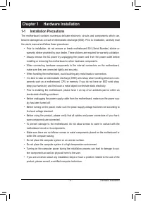
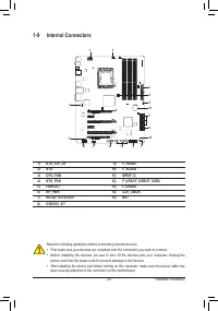
Hardware Installation
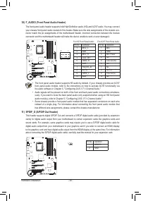
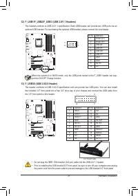
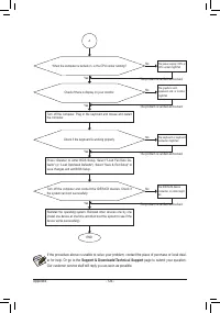
12) F_USB1/F_USB2/F_USB3 (USB 2.0/1.1 Headers)
The headers conform to USB 2.0/1.1 specification. Each USB header can provide two USB ports via an
optional USB bracket. For purchasing the optional USB bracket, please contact the local dealer.
DEBUG
PORT
G.QBOFM
10
9
2
1
When the system is in S4/S5 mode, only the USB ports routed to the F_USB1 header can sup-
port the ON/OFF Charge function.
Pin No.
Definition
1
Power (5V)
2
Power (5V)
3
USB DX-
4
USB DY-
5
USB DX+
6
USB DY+
7
GND
8
GND
9
No Pin
10
NC
•
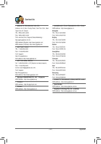
Do not plug the IEEE 1394 bracket (2x5-pin) cable into the USB 2.0/1.1 header.
•
Prior to installing the USB bracket/3.5" front panel, be sure to turn off your computer and unplug
the power cord from the power outlet to prevent damage to the USB bracket/3.5" front panel.
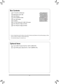
13) F_USB30 (USB 3.0/2.0 Header)
The header conforms to USB 3.0/2.0 specification and can provide two USB ports. You can also install
the included 3.5" front panel into a free 3.5" drive bay of your chassis and connect the USB cable from
the 3.5" front panel to this header.
F_USB30
F_AUDIO(H)
DB_PORT
F_PANEL(NH)
F_PANEL
(H61M-D2)
TPM
w/housing
Voltage measurement module(X58A-OC)
PCIe power connector (SATA)(X58A-OC)
DI
P
1
2
3
DIP
12
3
DI
P
1
2
3
DIP
1 2 3
1
1
1
1
BIOS Switcher (X58A-OC)
PWM Switch (X58A-OC)
10
11
20
1
Pin No.
Definition
Pin No.
Definition
1
VBUS
11
D2+
2
SSRX1-
12
D2-
3
SSRX1+
13
GND
4
GND
14
SSTX2+
5
SSTX1-
15
SSTX2-
6
SSTX1+
16
GND
7
GND
17
SSRX2+
8
D1-
18
SSRX2-
9
D1+
19
VBUS
10
NC
20
No Pin
3.5" Front Panel


