Материнские платы GIGABYTE G1 Guerrilla rev 1 0 - инструкция пользователя по применению, эксплуатации и установке на русском языке. Мы надеемся, она поможет вам решить возникшие у вас вопросы при эксплуатации техники.
Если остались вопросы, задайте их в комментариях после инструкции.
"Загружаем инструкцию", означает, что нужно подождать пока файл загрузится и можно будет его читать онлайн. Некоторые инструкции очень большие и время их появления зависит от вашей скорости интернета.
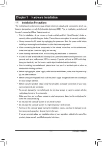
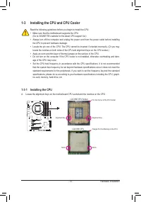
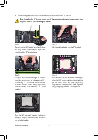
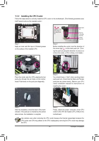
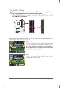
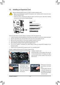
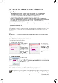
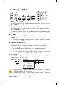
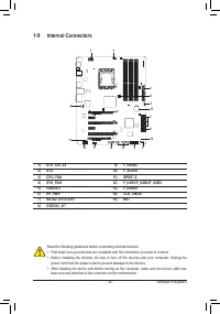


Hardware Installation
- 30 -
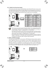
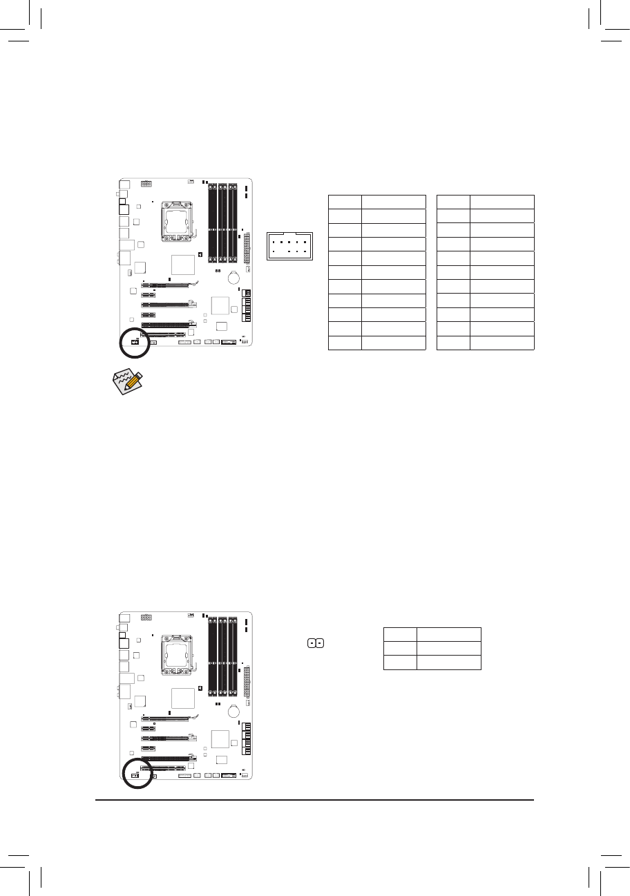
11) SPDIF_O (S/PDIF Out Header)
This header supports digital S/PDIF Out and connects a S/PDIF digital audio cable (provided by expansion
cards) for digital audio output from your motherboard to certain expansion cards like graphics cards and
sound cards. For example, some graphics cards may require you to use a S/PDIF digital audio cable for
digital audio output from your motherboard to your graphics card if you wish to connect an HDMI display
to the graphics card and have digital audio output from the HDMI display at the same time. For information
about connecting the S/PDIF digital audio cable, carefully read the manual for your expansion card.
Pin No.
Definition
1
SPDIFO
2
GND
1
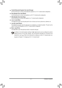
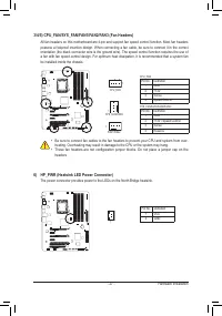
10) F_AUDIO (Front Panel Audio Header)
The front panel audio header supports Intel High Definition audio (HD) and AC'97 audio. You may connect
your chassis front panel audio module to this header. Make sure the wire assignments of the module con-
nector match the pin assignments of the motherboard header. Incorrect connection between the module
connector and the motherboard header will make the device unable to work or even damage it.
For HD Front Panel Audio: For AC'97 Front Panel Audio:
•
The front panel audio header supports HD audio by default. If your chassis provides an AC'97
front panel audio module, refer to the instructions on how to activate AC'97 functionality via
the audio software in Chapter 5, "Configuring 2/4/5.1/7.1-Channel Audio."
•
Audio signals will be present on both of the front and back panel audio connections simultane-
ously. If you want to mute the back panel audio (only supported when using an HD front panel
audio module), refer to Chapter 5, "Configuring 2/4/5.1/7.1-Channel Audio."
•
Some chassis provide a front panel audio module that has separated connectors on each wire
instead of a single plug. For information about connecting the front panel audio module that
has different wire assignments, please contact the chassis manufacturer.
Pin No.
Definition
1
MIC
2
GND
3
MIC Power
4
NC
5
Line Out (R)
6
NC
7
NC
8
No Pin
9
Line Out (L)
10
NC
Pin No.
Definition
1
MIC2_L
2
GND
3
MIC2_R
4
-ACZ_DET
5
LINE2_R
6
GND
7
FAUDIO_JD
8
No Pin
9
LINE2_L
10
GND
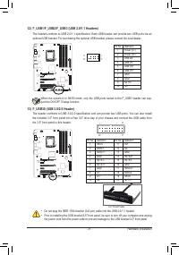
F_USB30
F_AUDIO(H)
DB_PORT
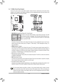
F_PANEL(NH)
F_PANEL
(H61M-D2)
TPM
w/housing
Voltage measurement module(X58A-OC)
PCIe power connector (SATA)(X58A-OC)
DI
P
1
2
3
DIP
12
3
DI
P
1
2
3
DIP
1 2 3
1
1
1
1
BIOS Switcher (X58A-OC)
PWM Switch (X58A-OC)
9
1
10
2


