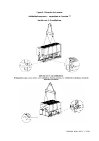
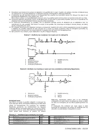
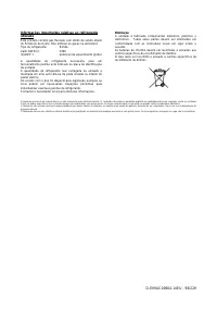
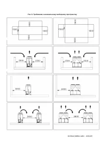
Кондиционеры Daikin EWAD-TZPR - инструкция пользователя по применению, эксплуатации и установке на русском языке. Мы надеемся, она поможет вам решить возникшие у вас вопросы при эксплуатации техники.
Если остались вопросы, задайте их в комментариях после инструкции.
"Загружаем инструкцию", означает, что нужно подождать пока файл загрузится и можно будет его читать онлайн. Некоторые инструкции очень большие и время их появления зависит от вашей скорости интернета.


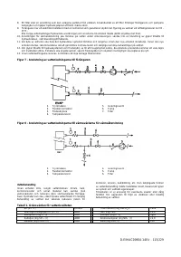

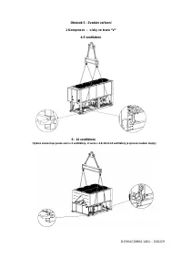


D–EIMAC00904–14EU - 17/229
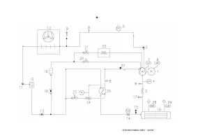
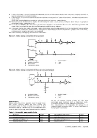
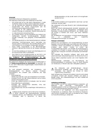
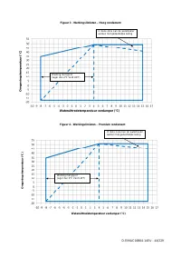
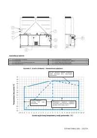
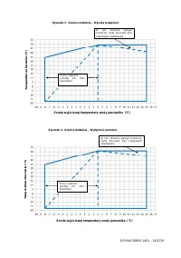
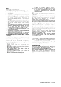
Evaporator and recovery exchangers anti-freeze protection
All evaporators are supplied with a thermostatically controlled
anti-freeze electrical resistance, which provides adequate anti-
freeze protection at temperatures as low as –25°C.
However, unless the heat exchangers are completely empty
and cleaned with anti-freeze solution, additional methods
should also be used against freezing.
Two or more of below protection methods should be
considered when designing the system as a whole:
−
Continuous water flow circulation inside piping and
exchangers
−
Addition of an appropriate amount of glycol inside the
water circuit
−
Additional heat insulation and heating of exposed piping
−
Emptying and cleaning of the heat exchanger during the
winter season
It is the responsibility of the installer and/or of local
maintenance personnel to ensure that described anti-freeze
methods are used. Make sure that appropriate anti-freeze
protection is maintained at all times. Failing to follow the
instructions above could result in unit damage. Damage
caused by freezing is not covered by the warranty.
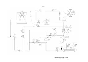
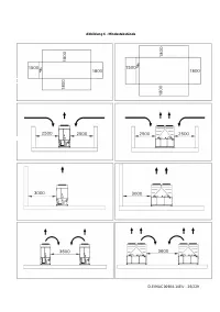
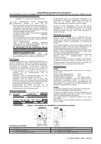
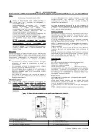
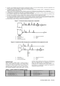
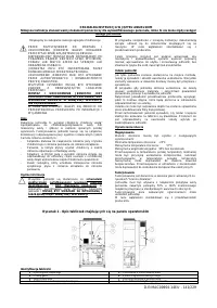
Installing the flow switch
To ensure sufficient water flow through the evaporator, it is
essential that a flow switch be installed on the water circuit.
The flow switch can be installed either on the inlet or outlet
water piping. The purpose of the flow switch is to stop the unit
in the event of interrupted water flow, thus protecting the
evaporator from freezing.
The manufacturer offers, as optional, a flow switch that has
been selected for this purpose.
This paddle-type flow switch is suitable for heavy-duty outdoor
applications (IP67) and pipe diameters in the range of 1” to 6”.
The flow switch is provided with a clean contact which must be
electrically connected to terminals shown in the wiring
diagram.
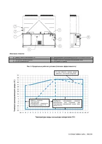
Flow switch has to be tune to intervene when the evaporator
water flow is lower than 50% of nominal flow rate.
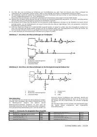
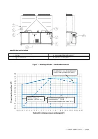
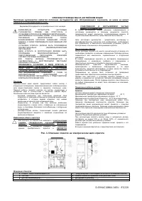
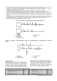
Heat recovery
Units may be optionally equipped with heat recovery system.
This system in made by a water cooled heat exchanger
located on the compressors discharge pipe and a dedicated
management of condensing pressure.
To guarantee compressor operation within its envelope, units
with heat recovery cannot operate with water temperature of
the heat recovery water lower than 28°C.
It is a responsibility of plant designer and chiller installer to
guarantee the respect of this value (e.g. using recirculating
bypass valve)
Electrical Installation
General specifications
All electrical connections to the unit must be carried out
in compliance with laws and regulations in force.
All installation, management and maintenance activities
must be carried out by qualified personnel.
Refer to the specific wiring diagram for the unit you have
bougth. Should the wiring diagram not be on the unit or
should it have been lost, please contact your
manufacturer representative, who will send you a copy.
In case of discrepance between wiring diagram and
electrical panel/cables, please contact the manufacturer
representative.
Only use copper conductors. Failure to use copper conductors
could result in overheating or corrosion at connection points
and could damage the unit.
To avoid interference, all control wires must be connected
separately from the power cables. Use different electrical
passage ducts for this purpose.
Particular care must be taken when realizing wire connections
to the switchbox; if not properly sealed, cable entries may
allow ingress of water into the switchbox which may cause
damage to the equipment inside.
Before any installation and connection works, the unit
must be switched off and secured. Since this unit
includes inverters, the intermediate circuit of the
capacitors remains charged with high voltage for a short
period of time after being switched off. Do not operate to
the unit before 5 minutes after the unit has been
switched off.
This unit includes non-linear loads such as inverters, which
have a natural current leakage to earth. If an Earth Leakage
Detector is installed upstream the unit, a type B device with a
minimum threshold of 300 mA must be used.
This product complies with EMC standards for industrial
environments. Therefore it is not intended for use in residential
areas, e.g. installations where the product is connected to a
low voltage public distribution system. Should this product
need to be connected to a low voltage public distribution
system, specific additional measures will have to be taken to
avoid interference with other sensitive equipment.
Operation
Operator’s responsibilities
It is essential that the operator is appropriately trained and
becomes familiar with the system before operating the unit. In
addition to reading this manual, the operator must study the
microprocessor operating manual and the wiring diagram in
order to understand start-up sequence, operation, shutdown
sequence and operation of all the safety devices.
During the unit’s initial start-up phase, a technician authorized
by the manufacturer is available to answer any questions and
to give instructions as to the correct operating procedures.
The operator must keep a record of operating data for every
installed unit. Another record should also be kept of all the
periodical maintenance and servicing activities.
If the operator notes abnormal or unusual operating conditions,
he is advised to consult the technical service authorized by the
manufacturer.
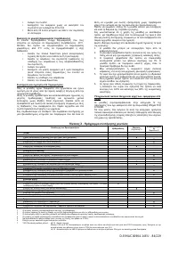
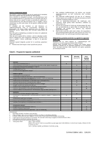
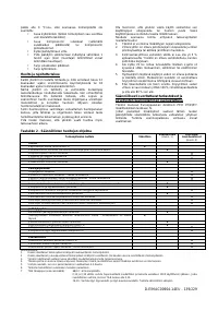
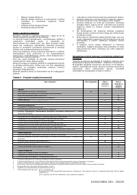
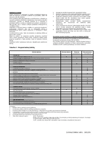
Routine maintenance
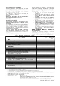
Minimum maintenance activities are listed in table 2.
Inverter Electrolytic Capacitors
Compressor Inverters include electrolytic capacitors which
have been designed to last a minimum of 15 years in normal
use. Heavy duty conditions may reduce the actual life of
capacitors.
The chiller calculates capacitor residual life based on actual
operation. When residual life gets below a give threshold, a
warning is issued by the controller. In this case replacement of
capacitors is recommended. This operation must be done only
by qualified technicians. Replacement must be carried out
through the following procedure:
•
Power off the chiller
•
Wait for 5 minutes before opening the inverter case
•
Check that residual dc voltage in the dc link is zero.
•
Open the inverter case and replace old capacitors
with new ones.
•
Reset the chiller controller through the maintenance
menu. This will allow the controller to recalculate the
new estimated life of the capacitors.
Capacitor Reforming after long shut-off period
Electrolytic capacitors may lose part of their original
characteristics if they are not powered for more than 1 year. If
chiller has been shut off for a longer period a “reforming”
procedure as follows is necessary:
•
Power on the inverter
•
Keep it powered on without starting the compressor
for at least 30 minutes
•
After 30 minutes the compressor can be started
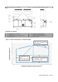
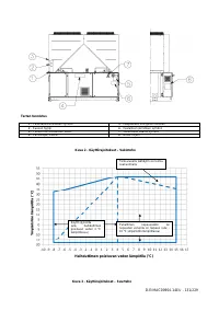
Low Ambient Start-up
Inverters include a temperature control which allows them to
withstand ambient temperatures down to -20°C. However they
should not be switched on at temperatures lower than 0°C
unless the following procedure is executed:


