Измерительные приборы Bosch GMS 120 - инструкция пользователя по применению, эксплуатации и установке на русском языке. Мы надеемся, она поможет вам решить возникшие у вас вопросы при эксплуатации техники.
Если остались вопросы, задайте их в комментариях после инструкции.
"Загружаем инструкцию", означает, что нужно подождать пока файл загрузится и можно будет его читать онлайн. Некоторые инструкции очень большие и время их появления зависит от вашей скорости интернета.

12
| English
2 609 140 939 | (8.3.12)
Bosch Power Tools
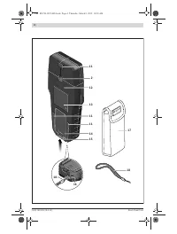
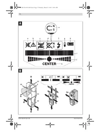
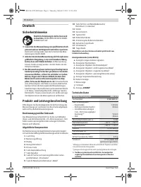
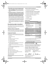
Method of Operation (see figures A – B)
The measuring tool checks the base material of sensor area
12
in measurement direction
A
to the max. detection depth
(see “Technical Data”). Objects are detected that differ from
the material of the wall.
Always move the measuring tool in a straight line over the sur-
face applying slight pressure, without lifting it off or changing
the pressure. During measurement, the contact pads
11
must
always have contact to the surface.
Measuring Procedure
Position the measuring tool on/against the surface being
detected, and move it in direction
B
. When the measuring tool
comes closer to an object, the amplitude in measuring indica-
tor
i
increases and ring
1
lights up yellow; when it is moved
away from the object, the amplitude decreases. Measuring
indicator
i
indicates the maximal amplitude above the centre
of the object; ring
1
lights up red and an audio signal sounds.
For small or deeply embedded objects, ring
1
can continue to
light up yellow, while there is no audio signal.
f
Wide objects are not indicated by the illuminated ring
or the audio signal throughout their complete width.
To localise the object more precisely, move the measuring
tool repeatedly (3x) back and forth over the object. The fine
scale
j
is automatically activated in all operating modes. Fine
scale
j
indicates a full amplitude when the object is below the
centre of the sensor or when the maximum amplitude of
measuring indicator
i
is reached. In the operating modes
“Drywall”
and
“Metal”
, the indication
“CENTER”
k
lights up
additionally.
Wider objects in the base material are detected through a
continuous, high amplitude of measuring indicators
i
and
j
.
Ring
1
lights up yellow. The duration of the high amplitude
corresponds approximately with the object width.
When very small or deeply embedded objects are being
sought and measuring indicator
i
reacts only slightly, move
the measuring tool repeatedly over the object in horizontal
and vertical direction. Pay attention to the amplitude of fine
scale
j
, and when in operating mode
“Drywall”
and
“Metal”
,
additionally to the
“CENTER ”
k
indication, which will then al-
low for precise detection.
f
Before drilling, sawing or routing into a wall, protect
yourself against hazards by using other information
sources.
As the measuring results can be influenced
through ambient conditions or the wall material, there may
be a hazard even though the indicator does not indicate an
object in the sensor range (no audio signal or beep and and
the illuminated ring
1
lit green).
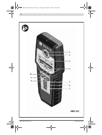
Operating Modes
The best measuring results are achieved through selection of
the operating modes. The maximal detection depth for metal
objects is achieved in the operating mode
“Metal”
. The max-
imal detection depth for “live” conductors is achieved in the
operating mode
“Power cable”
. The selected operating
mode can be recognized at any time via the green illuminated
operating-mode indication
4
.
Drywall
The operating mode
“Drywall”
is suitable for detecting wood
or metal objects in drywalls.
Press button
10
to activate the operating mode
“Drywall”
.
The operating-mode indication
4
above button
10
lights up
green. As soon as the measuring tool is positioned against the
base material to be detected, ring
1
lights up green and sig-
nals operational readiness.
In the operating mode
“Drywall”
all object types are detected
and indicated:
–
Non-metal, e. g. a wood beam
–
Magnetic, e. g. reinforcing steel
–
Non-magnetic, but metal, e. g. copper pipe
–
“Live”, e. g. a “live” conductor
Notes:
In the operating mode
“Drywall”
, other objects, apart
from wood and metal objects and “live” conductors are also
detected, such as plastic tubing filled with water. For such
objects, the indication
c
for non-metal objects is indicated in
display
3
.
Nails and screws in the base material may cause a wooden
beam to be indicated as a metal object on the display.
When display
3
indicates a continuously high amplitude of
measuring indicator
i
and fine scale
j
, restart the measuring
procedure again by positioning the measuring tool at a differ-
ent location on the base material.
When the illuminated ring
1
does not signal operational read-
iness when positioning the measuring tool on the base mate-
rial being detected, the measuring tool cannot properly de-
tect the base material.
– Press and hold button
10
until the illuminated ring lights up
green.
– When starting a new measuring procedure afterwards and
positioning the measuring tool onto a different wall or sur-
face, you must briefly press button
10
.
– In rare cases, the measuring tool may not be able to detect
the base material because the side with the sensor area
12
and the type plate
13
is soiled or dirty. Clean the measur-
ing tool with a dry, soft cloth and restart the measuring pro-
cedure.
Metal
The operating mode
“Metal”
is suitable for detecting magnet-
ic and non-magnetic objects independent of the wall material.
Press button
9
to activate the operating mode
“Metal”
. The il-
luminated ring
1
and indication
4
above button
9
light up
green.
When the detected metal object is of magnetic metal (e. g.
iron), the symbol
e
is indicated on display
3
. For non-magnet-
ic metals, the symbol
d
is indicated. In order to differentiate
between metal types, the measuring tool must be positioned
above the detected metal object (ring
1
is lit red).
Note:
For reinforcement steel mesh and steel in the examined
base material, an amplitude is indicated over the complete
surface of measuring indicator
i
. For reinforcement steel
mesh, it is typical that the symbol
e
for magnetic metal is indi-
cated on the display directly above the iron rods, whereas be-
tween the iron rods, the symbol
d
for non-magnetic metal will
appear.
OBJ_BUCH-1222-005.book Page 12 Thursday, March 8, 2012 11:26 AM
Характеристики

Остались вопросы?Не нашли свой ответ в руководстве или возникли другие проблемы? Задайте свой вопрос в форме ниже с подробным описанием вашей ситуации, чтобы другие люди и специалисты смогли дать на него ответ. Если вы знаете как решить проблему другого человека, пожалуйста, подскажите ему :)


