
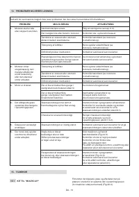
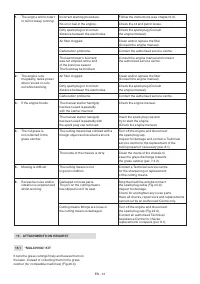
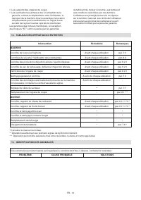
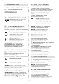
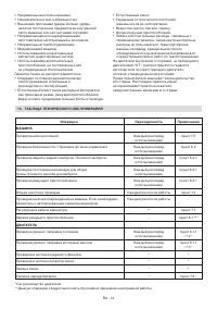
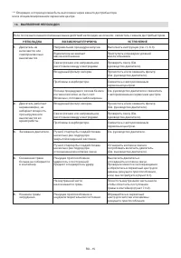
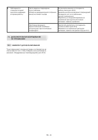
Газонокосилки STIGA Twinclip 950 V 294513048/ST1 - инструкция пользователя по применению, эксплуатации и установке на русском языке. Мы надеемся, она поможет вам решить возникшие у вас вопросы при эксплуатации техники.
Если остались вопросы, задайте их в комментариях после инструкции.
"Загружаем инструкцию", означает, что нужно подождать пока файл загрузится и можно будет его читать онлайн. Некоторые инструкции очень большие и время их появления зависит от вашей скорости интернета.


EN - 6
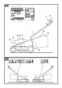
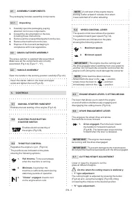
The cutting height is adjusted by using the
designated lever (Fig.9.C) that lifts or lowers
the chassis to the desired position.
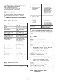
6. USING THE MACHINE
The safety regulations to follow are described in
chap. 2. Strictly comply with these indications to avoid
serious risks or dangers.
IMPORTANT
For instructions regarding the engine
and the battery (if supplied), read the relevant manuals.
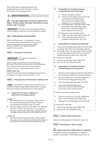
6.1 PRELIMINARY PROCEDURES
Before starting to work, it is necessary to carry
out several checks and operations to ensure you
can work efficiently and in maximum safety.
Place the machine in a stable horizontal
position on the ground.
6.1.1
Filling with oil and fuel
IMPORTANT
The machine is supplied
without engine oil or fuel.
Before using the machine for the first time after
purchase, fill with fuel and top up the oil tank following
the instructions and precautions provided in the
engine instruction manual and in par. 7.2/7.3.
Before each use
Check the fuel and oil levels following the instructions
provided in the engine manual and par. 7.2/7.3.
6.1.2
Preparing the machine before starting work
NOTE
This machine can be used to mow lawns in a
number of different ways; before starting work, prepare
the machine based on how the lawn is to be mowed.
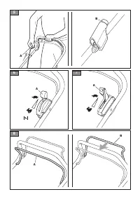
a.
Preparation for grass cutting and
collection in the grass catcher:
•
Type "I"
1.
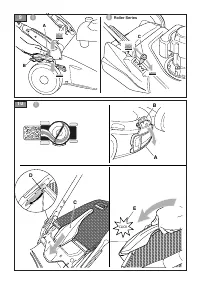
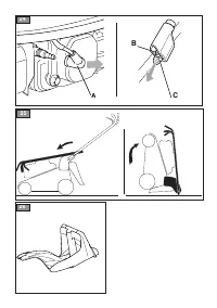
On models with a side discharge: make sure that
the side discharge guard (Fig.10.A) is lowered
and blocked by the safety lever (Fig.10.B).
2.
Insert the grass catcher as indicated in the diagram
(Fig.10.C). Position the side pins in the guides on
the base of the handle (Fig.10.D) and push the sack
forwards until you hear it click into place (Fig.10.E).
•
Type "II"
1.
Lift the rear discharge guard (Fig.11.A) and fasten
the grass catcher correctly, positioning the side pins
in the guides on the base of the handle (Fig.11.B).
b.
Preparation for mowing and grass
rear discharge onto the ground:
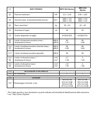
1.
Remove the grass catcher.
2.
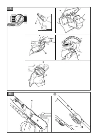
Lift the rear discharge guard (Fig.12.A)
and fit the rear discharge chute
(Fig.12.B) into the relative holes,
making sure it is securely in place.
3.
On models with a side discharge: make
sure that the side discharge guard
(Fig.12.C) is lowered and blocked
by the safety lever (Fig.12.D).
To remove the rear discharge chute:
1.
Lift the rear discharge guard (Fig.12.A).
2.
Lift the rear discharge chute and
release it from the holes (Fig.12.B).
c.
Preparation for mowing and mulching:
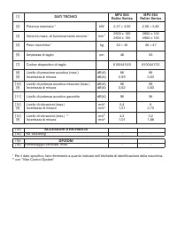
1.
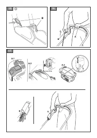
Lift the rear discharge guard (Fig.13.A) and fit the
chute flap (Fig.13.B) in the discharge opening.
2.
On models with a side discharge: make sure that
the side discharge guard (Fig.12.C) is lowered
and blocked by the safety lever (Fig.12.D).
To remove the chute flap:
1.
Lift the rear discharge guard (Fig.13.A).
2.
Remove the chute flap (Fig.13.B).
d.
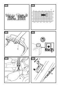
Preparation for mowing and grass
side discharge onto the ground:
1.
Lift the rear discharge guard (Fig.14.A) and fit the
chute flap (Fig.14.B) in the discharge opening.
2.
Push the safety lever (Fig.14.C) slightly and
lift the side discharge guard (Fig.14.D).
3.
Insert the side discharge chute (Fig.14.E).
4.
Close the side discharge guard
(Fig.14.D) so that the side discharge
chute (Fig.14.E) is locked in place.
To remove the side discharge chute:
5.
Push the safety lever (Fig.14.C) slightly and
lift the side discharge guard (Fig.14.D).
6.
Release the side discharge chute (Fig.14.E).
To remove the chute flap:
1.
Lift the rear discharge guard (Fig.14.A).
2.
Remove the chute flap (Fig.14.B).
6.1.3
Cutting height adjustment
Adjust the cutting height as indicated in (par. 5.7).
6.1.4
Adjusting the handle height
Do this when the cutting means is stationary.
The handle height can be adjusted to 3 different
positions, as marked on the handle base (Fig.15.A).


