
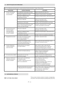
Газонокосилки STIGA Twinclip 950 V 294513048/ST1 - инструкция пользователя по применению, эксплуатации и установке на русском языке. Мы надеемся, она поможет вам решить возникшие у вас вопросы при эксплуатации техники.
Если остались вопросы, задайте их в комментариях после инструкции.
"Загружаем инструкцию", означает, что нужно подождать пока файл загрузится и можно будет его читать онлайн. Некоторые инструкции очень большие и время их появления зависит от вашей скорости интернета.


EN - 4
IMPORTANT
Improper use of the machine will
invalidate the warranty, relieve the Manufacturer from
all liabilities, and the user will consequently be liable
for all and any damage or injury to himself or others.
3.1.3 User types
This machine is intended for use by consumers,
i.e. non-professional operators.
It is intended for "DIY" use only.
IMPORTANT
The machine must
be used by one operator.
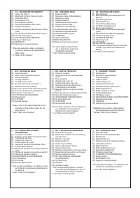
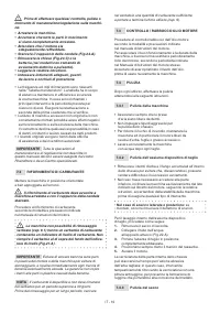
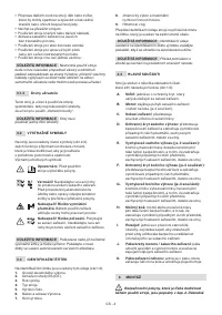
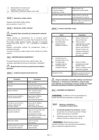
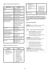
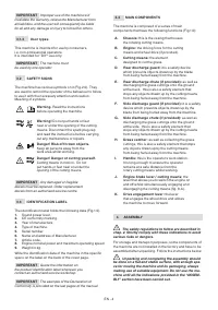
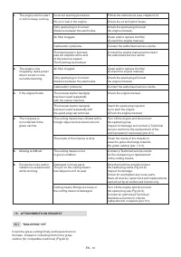
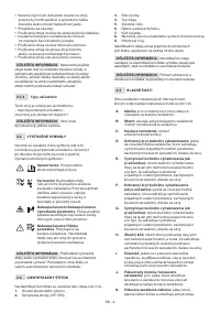
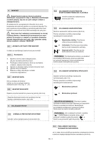
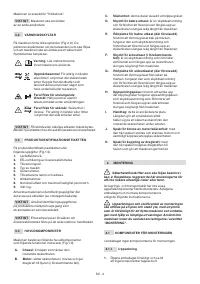
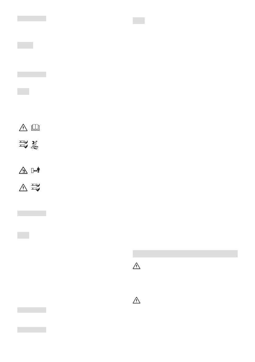
3.2 SAFETY SIGNS
The machine has various symbols on it (Fig.2.0). They
are used to remind the operator of the behaviour to follow
to use it with the necessary attention and caution.
Meaning of symbols:
Warning.
Read the instructions
before operating the machine.
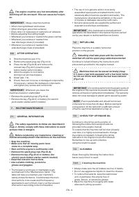
Warning!
Do not put hands or feet
near or under the opening of the cutting
means. Disconnect the spark plug cap
and read the instructions before carrying
out any maintenance or repairs.
Danger! Risk of thrown objects.
Keep all persons away from the
work area whilst working.
Danger! Danger of cutting yourself.
Cutting means in motion. Do not
put hands or feet near or under the
opening of the cutting means.
IMPORTANT
Any damaged or illegible
decals must be replaced. Order replacement
decals from an authorised service centre.
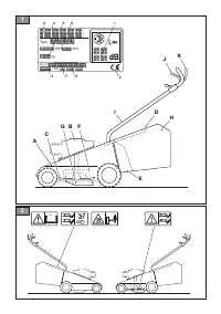
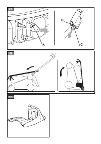
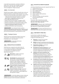
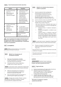
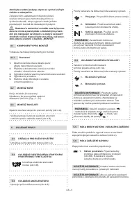
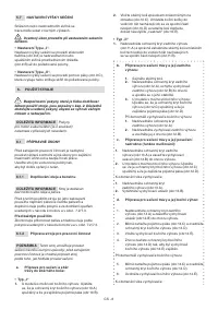
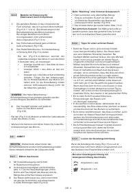
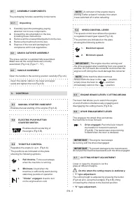
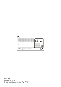
3.3 IDENTIFICATION LABEL
The identification label holds the following data (Fig.1.0).
1.
Sound power level.
2.
CE conformity marking.
3.
Year of manufacture.
4.
Type of machine.
5.
Serial number.
6.
Name and address of Manufacturer.
7.
Article code.
8.
Engine nominal power and maximum operating speed
9.
Weight in kg.
Write the identification data of the machine in the specific
space on the label on the back of the cover page.
IMPORTANT
Quote the information on
the product identification label whenever you
contact an authorised service workshop.
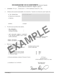
IMPORTANT
The example of the Declaration of
Conformity is provided on the last pages of the manual.
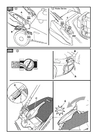
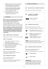
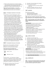
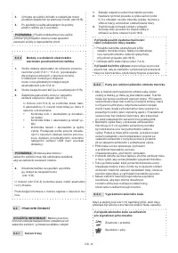
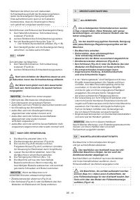
3.4 MAIN COMPONENTS
The machine is composed of a series of main
components that have the following functions (Fig.1.0):
A.
Chassis:
this is the casing that houses
the rotating cutting means.
B.
Engine:
the driving force for the cutting
means and wheel drive (if provided).
C.
Cutting means:
the element
designed to cut the grass.
D.
Rear discharge guard:
it is a safety device
which prevents objects drawn up by the blade
from being hurled away from the machine.
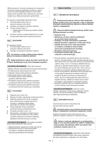
E.
Rear discharge chute (if provided):
as well as
discharging the grass cuttings onto the ground
at the back, this is also a safety element that
stops any objects drawn up by the cutting means
from being hurled away from the machine.
F.
Side discharge guard (if provided):
it is a safety
device which prevents objects drawn up by the
blade from being hurled away from the machine.
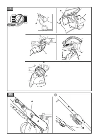
G.
Side discharge chute (if provided):
as well as
discharging the grass cuttings onto the ground
at the side, this is also a safety element that
stops any objects drawn up by the cutting means
from being hurled away from the machine.
H.
Grass catcher:
as well as collecting the grass
cuttings, this is also a safety element that stops
any objects drawn up by the cutting means
from being hurled away from the machine.
I.
Handle:
this is the operator’s work station.
It is long enough to ensure the operator
remains at a safe distance from the
rotary cutting means whilst working.
J.
Engine brake lever / cutting means:
the
lever that allows you to switch the engine on
and off whilst simultaneously engaging and
disengaging the cutting means (fig. 8.A).
K.
Drive engagement lever:
the lever
that engages the wheel drive and allows
the machine to move forward.
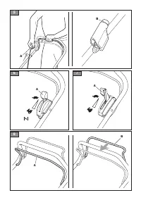
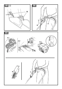
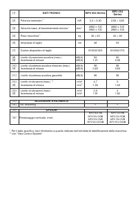
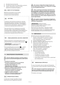
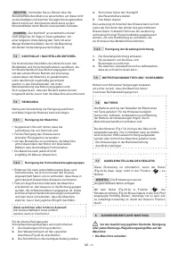
4. ASSEMBLY
The safety regulations to follow are described in
chap. 2. Strictly comply with these indications to avoid
serious risks or dangers.
For storage and transport purposes, some components of
the machine are not installed in the factory and have to be
assembled after unpacking. Follow the instructions below.
Unpacking and completing the assembly should
be done on a flat and stable surface, with enough spa
-
ce for moving the machine and its packaging, always
making use of suitable equipment. Do not use the ma-
chine until all the indications provided in the “ASSEM-
BLY” section have been carried out.


