
Варочная панель Kuppersberg FV3XE - инструкция пользователя по применению, эксплуатации и установке на русском языке. Мы надеемся, она поможет вам решить возникшие у вас вопросы при эксплуатации техники.
Если остались вопросы, задайте их в комментариях после инструкции.
"Загружаем инструкцию", означает, что нужно подождать пока файл загрузится и можно будет его читать онлайн. Некоторые инструкции очень большие и время их появления зависит от вашей скорости интернета.
12
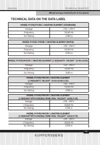
Technical passporT
english
Mixed and gas fuelled built-in hot plates
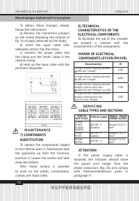
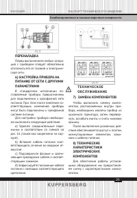
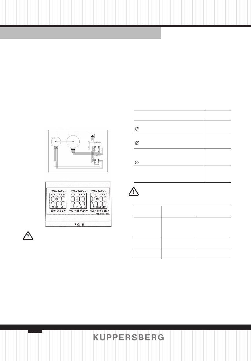
To obtain these changes, please,
follow the instructions:
a) Remove the connection jumpers
on the clamp following the scheme of
fi g. 16 of page (attached on the body).
b) Insert the input cable with
adequate section into the chock.
c) Connect the phase cable into
the clamp and the “earth” cable in the
relative clamp.
d) Hold up the input cable with the
pertinent stopcable.
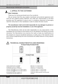
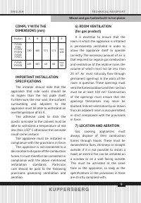
8) TECHNICAL
CHARACTERISTICS OF THE
ELECTRICAL COMPONENTS
To facilitate the job of the installer
we present a scheme with the
characteristics of the components.
Denominations
W
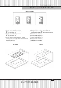
Hi-light electric heating element
140 mm "Hilight”
1200
Hi-light electric heating element
180 mm "Hilight"
1800
Hi-light electric heating element
double cooking zone conc.
180/120 mm ("Hilight" as well)
1700
Hi-light electric heating element
double cooking zone oval
265/170 mm "Hilight"
2400
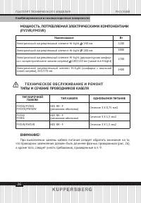
POWER OF ELECTRICAL
COMPONENTS (FV3VR/FM3VR)
M A I N T E N A N C E
7) COMPONENTS
SUBSTITUTION
To replace the components lodged
in the internal part, is necessaryto take
the appliance up from the furniture,
overturn it, loosen the sorews and take
away the bottom.
After these actions is possible
to work on the plates, commutators,
clamps and input cable.
S E RV I C I N G
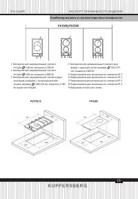
CABLE TYPES AND SECTIONS
TYPE OF
HOT PLATE TYPE OF CABLE
SINGLE - PHASE
POWER SUPPLY
FV3XG/
FV3EG
FV3XW/
FW3EW
H05 RR - F
(Rubber)
Section 3 X 0.75
mm2
FV3XE
FV3EE
H05 RR - F
Rubber)
Section 3 X 1.5
mm2
FV3VR/
FM3VR
H05 RR - F
Section 3 X 1.5
mm2
ATTENTION
If the power supply cable is
leplaced, the Installer should leave
the gound wire longer than the
phase conductors (fi g. 26) and comply
with theecommendations given in
paragraph 9.
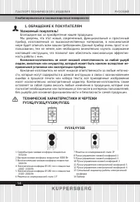
Содержание
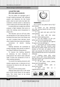
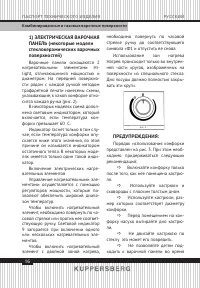
- 16 ) ЭЛЕКТРИЧЕСКАЯ ВАРОЧНАЯ
- 17 Э КС П Л УАТА Ц И Я
- 18 Ч И С Т К А
- 20 Прибор относится к оборудованию
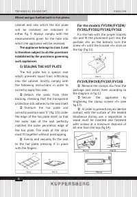
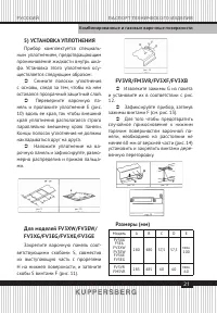
- 21 ) УСТАНОВКА УПЛОТНЕНИЯ
- 22 УКАЗАНИЯ ПО УСТАНОВКЕ; При установке следует учесть, что
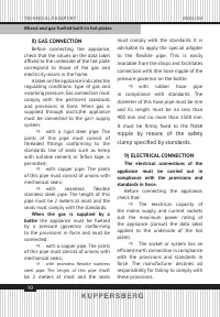
- 23 ) ПОДКЛЮЧЕНИЕ К ГАЗОВОЙ; Если используется газ из баллона; ) ПОДКЛЮЧЕНИЕ К СЕТИ
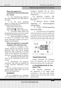
- 24 Если подключение
- 26 МОЩНОСТЬ, ПОТРЕБЛЯЕМАЯ ЭЛЕКТРИЧЕСКИМИ КОМПОНЕНТАМИ; Т Е Х Н И Ч Е С КО Е О Б С Л УЖ И В А Н И Е И Р Е М О Н Т
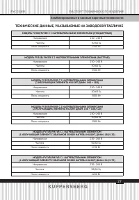
- 27 ТЕХНИЧЕСКИЕ ДАННЫЕ, УКАЗЫВАЕМЫЕ НА ЗАВОДСКОЙ ТАБЛИЧКЕ
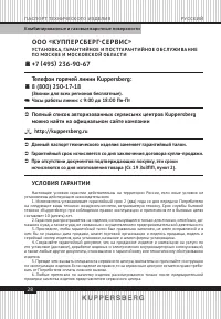
- 28 О О О; УС ТА Н О В КА, ГА РА Н Т И Й Н О Е И П О С Т ГА РА Н Т И Й Н О Е О Б С Л УЖ И В А Н И Е; Телефон горячей линии Kuppersberg:; Полный список авторизованных сервисынх центров Kuppersberg; УСЛОВИЯ ГАРАНТИИ


