
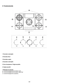
Варочная панель Elica NIKOLATESLA FLAME GR/A/88 - инструкция пользователя по применению, эксплуатации и установке на русском языке. Мы надеемся, она поможет вам решить возникшие у вас вопросы при эксплуатации техники.
Если остались вопросы, задайте их в комментариях после инструкции.
"Загружаем инструкцию", означает, что нужно подождать пока файл загрузится и можно будет его читать онлайн. Некоторые инструкции очень большие и время их появления зависит от вашей скорости интернета.


72
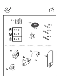
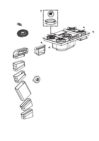
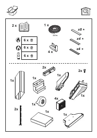
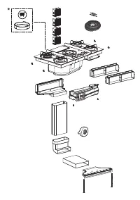
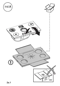
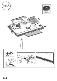
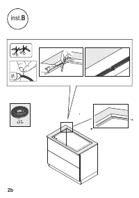
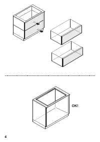
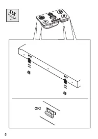
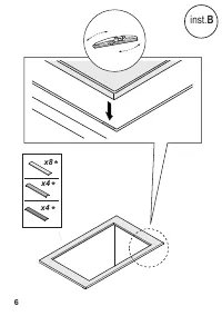
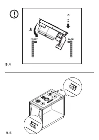
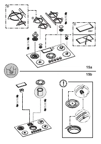
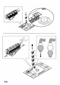
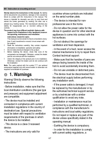
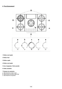
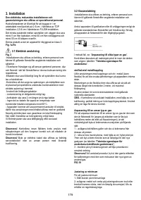
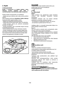
3. Installation
The electrical and mechanical installation and gas
connection must be carried out by specialised personnel.
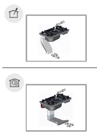
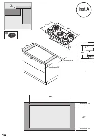
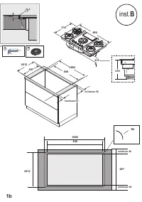
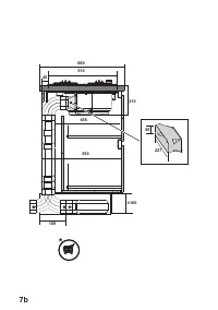
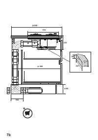
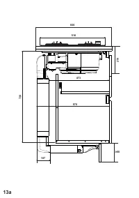
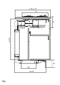
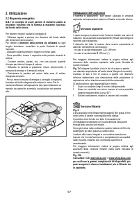
The electrical appliance is designed to be built-in to a 2-6 cm
thick worktop in the case of TOP installations; 2.5-6 cm in the
case of FLUSH installations.
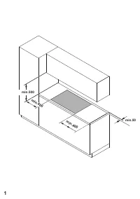
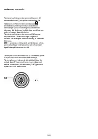
The minimum distance between the hob and the wall must be
at least 5 cm from the rear part, at least 40 cm from the side
walls and at least 50 cm from the wall units above.
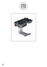
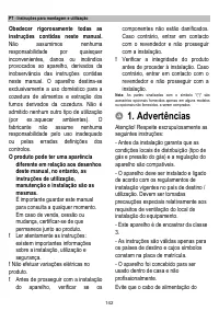
This product is a class 3 recessed appliance.
Fig. 1a /1b
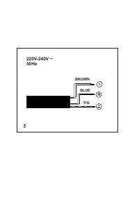
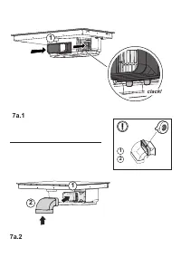
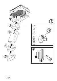
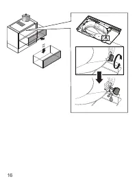
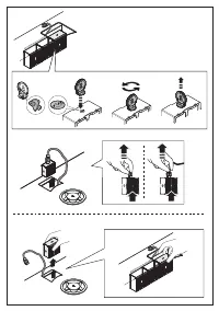
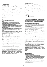
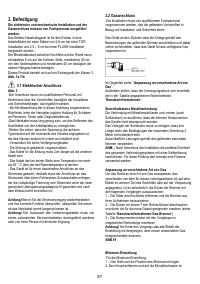
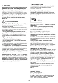
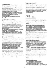
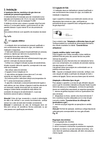
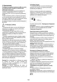
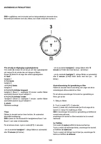
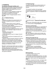
3.1 Electrical connection
Fig. 3
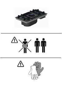
-The installation must be performed by professionally qualified
personnel familiar with the applicable installation and safety
standards.
- The manufacturer declines all responsibility to persons,
animals or property if the guidelines provided in this handbook
are not followed.
-The power cable must be long enough to allow removal of the
hob from the worktop
-Make sure that the voltage on the rating plate on the bottom
of the device corresponds to that of the house where it will be
installed.
-Do not use extension cords.
- Earthing is required by law
- The earth power cable must be 2cm longer than the other
cables
- At no point along the length of the cable must it reach a
temperature of 50° C above the room temperature.
- The device is intended to be permanently connected to the
electrical network, therefore, make the connection to the fixed
network via a standard omnipolar switch, which assures the
complete disconnection of the mains under category III over-
voltage conditions, and which is readily accessible after the
installation.
Caution!
Before reconnecting the circuit to the mains power
supply and checking its correct operation, always check that
the network cable has been correctly assembled.
Caution!
The interconnection cable must be replaced by
authorised customer service personnel or equally qualified
person.
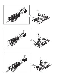
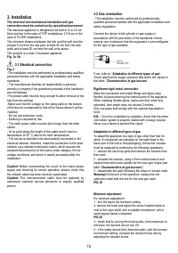
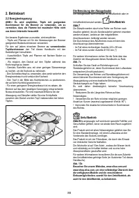
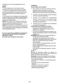
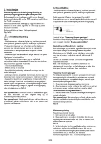
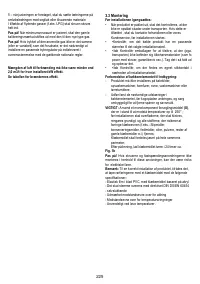
3.2 Gas connection
- The installation must be performed by professionally
qualified personnel familiar with the applicable installation and
safety regulations.
Connect the device to the cylinder or gas supply in
accordance with the provisions of the standards in force,
making sure in advance that the equipment is pre-configured
for the type of gas available.
If not, refer to: “
Adaptation to different types of gas
”.
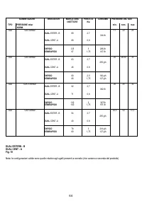
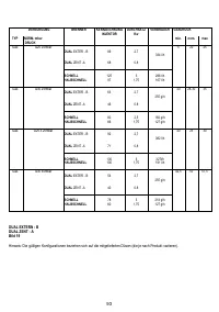
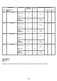
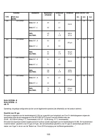
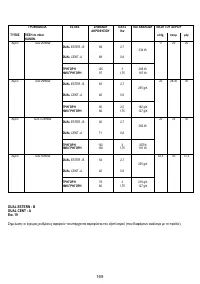
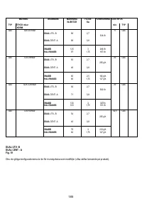
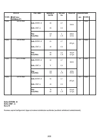
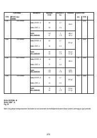
Check also that the supply pressure falls within the values in
the table: “
Characteristics of gas burners
”.
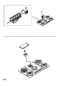
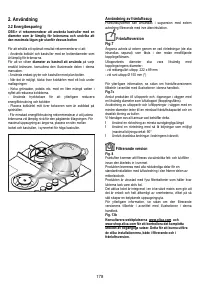
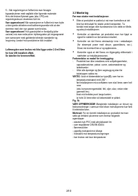
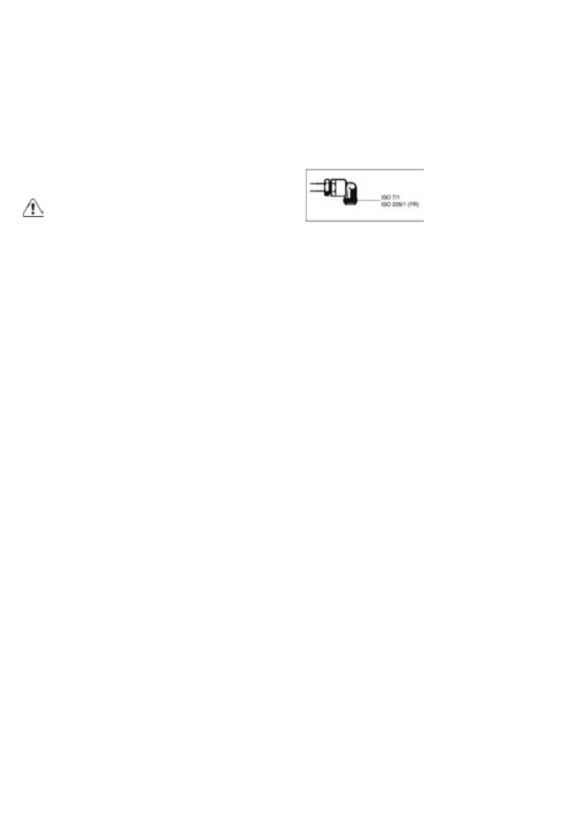
Rigid/semi-rigid metal connection
Make the connection with metal fittings and pipes (also
flexible) to avoid straining the internal parts of the appliance.
When installing flexible pipes, make sure that, when fully
extended, their length does not exceed 2 metres.
Only use pipes that comply with the national standards in
force.
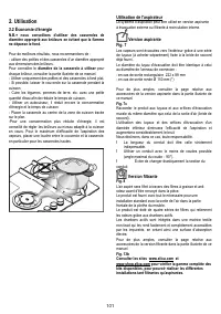
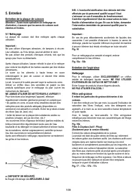
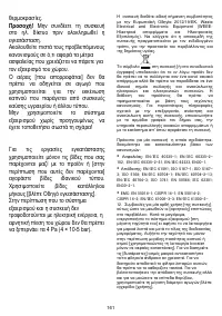
N.B. -
Once the installation is complete, check that the entire
connection system is properly sealed with a soapy solution.
Never use a flame to perform this check.
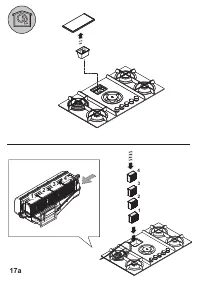
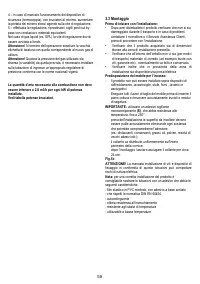
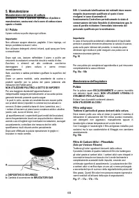
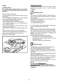
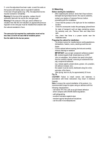
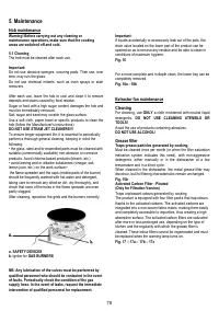
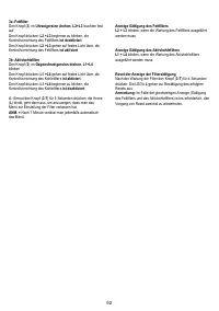
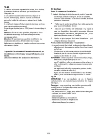
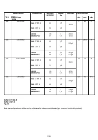
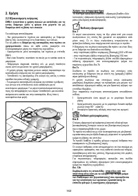
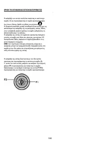
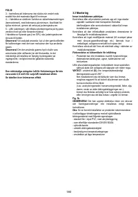
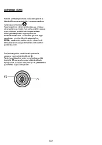
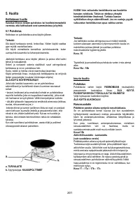
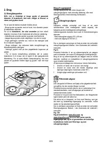
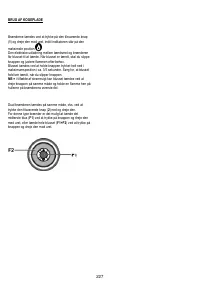
Adaptation to different types of gas
To adapt the appliance to a type of gas other than that for
which it is designed (as indicated on the label fixed to the
lower part of the hob or the packaging), the burner nozzles
must be replaced by performing the following operations:
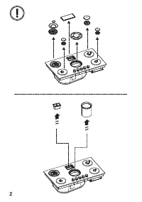
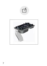
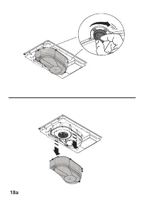
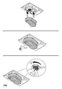
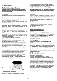
1 - remove the stove top grids and remove the burners from
their slots
2 - unscrew the nozzles, using a 7mm socket wrench and
replace them with ones suitable for the new type of gas (see
table “
Characteristics of gas burners
“)
3 - reassemble the parts following the steps in reverse order
Warning!
At the end of the operation, replace the old
calibration label with the one for the new gas used.
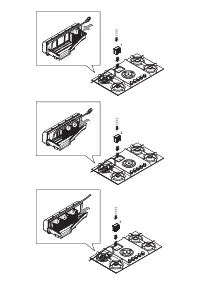
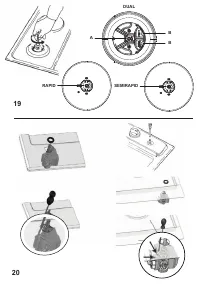
FIG.19
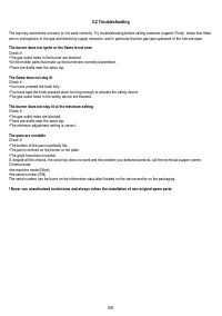
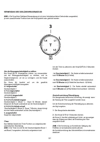
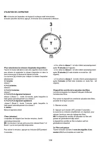
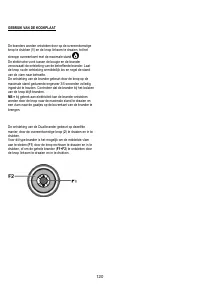
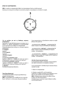
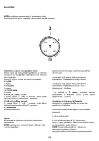
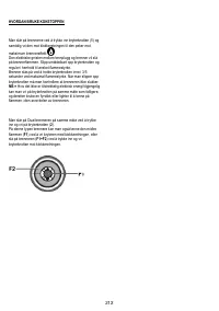
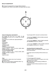
Minimum adjustment
For minimum adjustment:
1 - turn the tap to the minimum setting
2- remove the knob and adjust the screw located inside or
next to the valve shaft, with a suitable screwdriver, until a
small regular flame is obtained
FIG.20
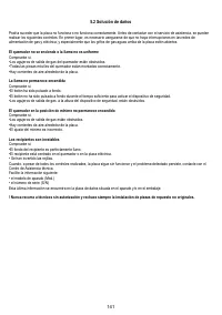
3 - check that by turning the knob quickly, from maximum to
minimum, the burners do not turn off
4 - if the safety device fails (thermocouple), with the burners
on minimum setting, increase the minimum flow rate by
adjusting the relevant screw.
Характеристики

Остались вопросы?Не нашли свой ответ в руководстве или возникли другие проблемы? Задайте свой вопрос в форме ниже с подробным описанием вашей ситуации, чтобы другие люди и специалисты смогли дать на него ответ. Если вы знаете как решить проблему другого человека, пожалуйста, подскажите ему :)


