
Триммеры Hitachi CG31EBS - инструкция пользователя по применению, эксплуатации и установке на русском языке. Мы надеемся, она поможет вам решить возникшие у вас вопросы при эксплуатации техники.
Если остались вопросы, задайте их в комментариях после инструкции.
"Загружаем инструкцию", означает, что нужно подождать пока файл загрузится и можно будет его читать онлайн. Некоторые инструкции очень большие и время их появления зависит от вашей скорости интернета.


12
English
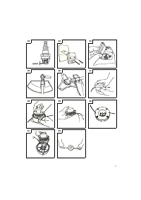
Carburetor
adjustment
(
Fig.
29
)
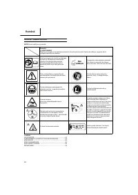
WARNING
○
The cutting attachment may be spinning during carburetor
adjustments.
○
Never star t the engine without the complete clutch cover and
tube assembled! Other wise the clutch can come loose and
cause personal injuries.
In the carburetor, fuel is mixed with air. When the engine is test
run at the factor y, the carburetor is basically adjusted. A fur ther
adjustment may be required, according to climate and altitude. The
carburetor has one adjustment possibility:
T
=
Idle
speed
adjustment
screw.
Idle
speed
adjustment
(
T
)
Check that the air
fi
lter is clean. When the idle speed is correct, the
cutting attachment will not rotate. If adjustment is required, close
(clockwise) the T-screw, with the engine running, until the cutting
attachment star ts to rotate. Open (counter-clockwise) the screw
until the cutting attachment stops. You have reached the correct idle
speed when the engine runs smoothly in all positions well below the
rpm when the cutting attachment star ts to rotate.
If the cutting attachment still rotates after idle speed adjustment,
contact your Hitachi dealer.
NOTE
Standard Idle rpm is 2200 –2800 rpm.
WARNING
When the engine is idling the cutting attachment must under no
circumstances rotate.
Air
fi
lter
(
Fig.
30
)
The air
fi
lter must be cleaned from dust and dir t in order to avoid:
○
Carburetor
malfunctions
○
Star ting
problems
○
Engine power reduction
○
Unnecessar y wear on the engine par ts
○
Abnormal fuel consumption
Clean the air
fi
lter daily or more often if working in exceptionally
dusty areas.
Cleaning
the
air
fi
lter
Remove the air
fi
lter cover and the
fi
lter (19). Rinse it in warm soap
suds. Check that the
fi
lter is dr y before reassembly. An air
fi
lter
that has been used for some time cannot be cleaned completely.
Therefore, it must regularly be replaced with a new one. A damaged
fi
lter must always be replaced.
Fuel
fi
lter
(
Fig.
31
)
Drain all fuel from fuel tank and pull fuel
fi
lter line from tank. Pull
fi
lter element out of holder assembly and rinse element in warm
water with detergent.
Rinse thoroughly until all traces of detergent are eliminated.
Squeeze, do not wring, away excess water and allow element to air
dr y.
NOTE
If element is hard due to excessive dir t buildup, replace it.
Spark
plug
(
Fig.
32
)
The spark plug condition is in
fl
uenced by:
○
An incorrect carburetor setting
○
Wrong fuel mixture (too much oil in the gasoline)
○
A dir ty air
fi
lter
○
Hard running conditions (such as cold weather)
These factors cause deposits on the spark plug electrodes, which
may result in malfunction and star ting di
ffi
culties. If the engine
is low on power, di
ffi
cult to star t or runs poorly at idling speed,
always check the spark plug
fi
rst. If the spark plug is dir ty, clean it
and check the electrode gap. Re-adjust if necessar y. The correct
gap is 0.6 mm. The spark plug should be replaced after about 100
operation hours or earlier if the electrodes are badly eroded.
Mu
ffl
er
(
Fig.
33
)
Remove the mu
ffl
er and clean out any excess carbon from the
exhaust por t or mu
ffl
er inlet ever y 100 hours of operation.
Cylinder
(
Engine
cooling
) (
Fig.
34
)
The engine is air cooled, and air must circulate freely around engine
and over cooling
fi
ns on cylinder head to prevent overheating.
Ever y 100 operating hours, or once a year (more often if conditions
require), clean
fi
ns and external sur faces of engine of dust, dir t and
oil deposits which can contribute to improper cooling.
NOTE
Do not operate engine with engine shroud or mu
ffl
er guard
removed as this will cause overheating and engine damage.
Angle
transmission
(
Fig.
35
)
Check angle transmission or angle gear for grease level about ever y
50 hours of operation by removing the grease
fi
ller plug on the side
of angle transmission.
If no grease can be seen on the
fl
anks of the gears,
fi
ll the
transmission with quality lithium based multipurpose grease up to
3/4. Do not completely
fi
ll the transmission.
Blade
WARNING
Wear protective gloves when handling or per forming
maintenance on the blade. (
Fig.
36
)
○
Use a sharp blade. A dull blade is more likely to snag and thrust.
Replace the fastening nut if it is damaged and hard to tighten.
○
When replacing blade, purchase one recommended by Hitachi,
with a 25.4 mm (one inch)
fi
tting hole.
○
When installing a saw blade, always face the stamped side up.
In the case of a 3 tooth blade, it can be used on either side.
○
Use the correct blade for the type of work.
○
When replacing blades, use appropriate tools.
○
When cutting edges become dull, re-sharpen or
fi
le as shown
in the illustration. Incorrect sharpening may cause excessive
vibration.
○
Discard blades that are bent, warped, cracked, broken or
damaged in any way.
NOTE
When sharpening blade it is impor tant to maintain an original
shape of radius at the base of the tooth to avoid cracking.
Nylon
head
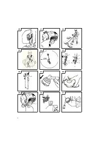
Nylon line replacement
○
Remove the cutting body cap by pushing inward the locking
tabs on the side of the nylon head (
Fig.
37
). Take out the spool
(
Fig.
38
), hook the new nylon line into the hole of the spool, then
wind it around the spool in two stages (
Fig.
39
).
When the nylon line has been wound around the spool,
temporarily fasten it in the opening of the spool at about 10 cm
from the end. (
Fig.
40
) Then thread the nylon line through the
hole on the side of the nylon head and place the cutting body
cap in reverse order of the cap removal. Pull the right and left
nylon lines until they are secured about 15
–
16 cm from the end.
(
Fig.
42
)
NOTE
○
The nylon head is designed for nylon lines with an outer
diameter of 2.5 mm. Do not use nylon lines with a di
ff
erent outer
diameter.
○
Make sure that the right and left nylon lines are of equal length
since vibrations will other wise increase.
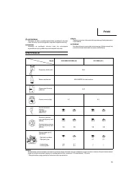
Maintenance
schedule
Below you will
fi
nd some general maintenance instructions. For
fur ther information please contact your Hitachi dealer.
Daily
maintenance
○
Clean the exterior of the unit.
○
Check that the harness is undamaged.
○
Check the blade guard for damage or cracks. Change the guard
in case of impacts or cracks.
000Book̲CG31EBS̲EE.indb 12
000Book̲CG31EBS̲EE.indb 12
2009/10/15 9:13:39
2009/10/15 9:13:39


