
Триммеры Hitachi CG31EBS - инструкция пользователя по применению, эксплуатации и установке на русском языке. Мы надеемся, она поможет вам решить возникшие у вас вопросы при эксплуатации техники.
Если остались вопросы, задайте их в комментариях после инструкции.
"Загружаем инструкцию", означает, что нужно подождать пока файл загрузится и можно будет его читать онлайн. Некоторые инструкции очень большие и время их появления зависит от вашей скорости интернета.


10
English
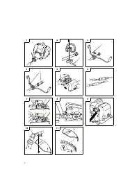
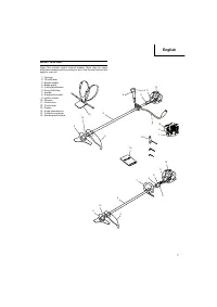
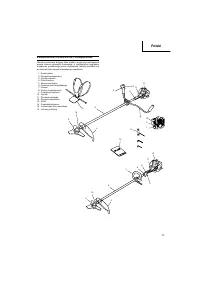
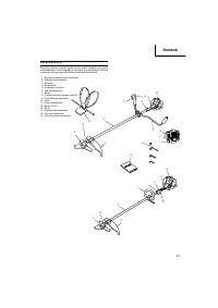
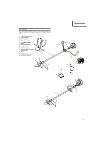
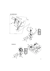
ASSEMBLY
PROCEDURES
Drive
shaft
to
engine
(
Fig.
1
)
Loosen tube locking bolt (1) about ten turns so that the bolt point will
not obstruct drive shaft tube to be inser ted. When inser ting drive
shaft tube, hold the tube locking bolt outward preventing inside
fi
tting from obstructing as well.
Some models may come with the drive shaft already installed.
NOTE
When it is hard to inser t drive shaft up to the marked position on
the drive shaft tube, turn drive shaft by the cutter mounting end
clockwise or counter-clockwise. Tighten tube locking bolt lining
up the hole in the shaft tube. Then tighten clamp bolt securely
(1).
Installation
of
handle
WARNING
When you use steel/rigid blades on straight shaft trimmers or
brush cutters, always use a barrier bar (2) and shoulder harness
with the loop handle. (
Fig.
2
)
Attach the handle to the drive shaft tube with the angle towards the
engine.
Adjust the location to the most comfor table position before
operation.
NOTE
If your unit has handle location label on drive shaft tube, follow
indication.
Remove the handle bracket (3) from the assembly. (
Fig.
3
)
Place the handles and attach the handle bracket with four bolts
lightly. Adjust to appropriate position. Then attach it
fi
rmly with the
bolts.
Attach the protection tube to the drive shaft or handle using cord
clamps (4). (
Fig.
4
)
NOTE
If the protection tube is set apar t from the handle or pipe, it will
be caught by something during operation and it may cause
serious injur y. Do not set the protection tube apar t from the
handle or pipe.
Throttle
wire
/
stop
cord
Remove air cleaner cover. (
Fig.
5
)
Loosen and remove the screw from the throttle wire holder. (
Fig.
7
)
Connect the terminals of the stop cords coming out from the engine
and shaft. (
Fig.
6
)
Hook the throttle wire end on the throttle of the carburetor.
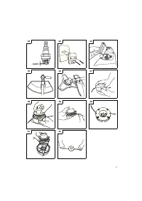
Make sure that the throttle trigger shown in
Fig.
18
has returned to
the star ting position.
Put the throttle outer end into the groove, and then cover it with the
throttle wire holder and
fi
x the holder with the screw. (
Fig.
8
)
Then, install the cleaner cover.
Fix the protection tube which the stop cords and throttle wire are
passing through, on the pipe with the hip pad. Then, as shown in the
fi
gure,
fi
x the protection tube on the pipe and handle with the bands
in the bag.
After
fi
xing, cut o
ff
the extra par t of the band not to obstruct the
operation. (
Fig.
4
)
NOTE
If the protection tube is set apar t from the handle or pipe, it will
be caught by something during operation and it may cause
serious injur y.
Do not set the protection tube apar t from the handle or pipe.
Some models may come with the par ts pre-installed.
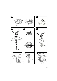
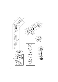
Installation
of
blade
guard
(
Fig.
10
)
The guard bracket already mounted to the drive shaft tube.
Attach
the
gear
case
cover
with
the
three
screws
.
Install the blade guard on drive shaft tube against angle
transmission (5). Tighten the guard bracket
fi
rmly so that the blade
guard does not swing or move down during operation.
CAUTION
The blade guard must be in place during operation.
If the blade guard is not in place, there is a possibility of serious
injur y.
Blade guards are equipped with sharp line limiter. Be careful with
handling it.
NOTE
○
When attaching the guard extension to the blade guard, the
sharp line limiter must be removed from the blade guard.
○
To remove the guard extension, refer to the drawings. Wear
gloves as the extension has a sharp line limiter, then push the
two square tabs on the guard one by one in order after removed
the screw. (
Fig.
12
)
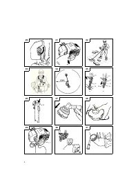
Installation
of
cutting
blade
(
Fig.
13
)
When installing a cutting blade, make sure that there are no cracks
or any damage in it and that the cutting edges are facing the correct
direction.
Align the notch hole of the cutter holder with the hole on the gear
case (Top the gear case) and inser t the Allen wrench to stop turning.
Turn the
fi
xing nut clockwise and remove the
fi
xing nut, protection
cover, cutter holder cap, and toothed lock washers.
The installation of the cutting blade is as follows: inser t the Allen
wrench into the notch hole of the cutter holder and the hole on
the gear case. Then, install the cutting blade (check the installing
direction, as referring to
Fig.
15
), the cutter holder cap, protection
cover, and toothed lock washers onto the cutter holder in this order.
Finally, tighten the
fi
xing nut securely by turning counterclockwise
with the Combi box spanner. (
Fig.
13
)
CAUTION
○
When installing the cutting blade, set its center hole to the
convex par t of the cutter holder and hold it with the concave
sur face of the cutter holder cap. Then, tighten the
fi
xing nut to
prevent the cutting blade from being eccentric. (
Fig.
14
)
After installing the cutting blade, be sure to remove the Allen
wrench and Combi box spanner.
○
Before operation, make sure the blade has been properly
installed.
○
Cutter holder cap under a cutting blade, check it for wear
or cracks before operation. If any damage or wear is found,
replace it, as it is an ar ticle of consumption.
NOTE
The blade must be retained with a new cotter pin each time
installed. (
Fig.
13
)
Installation
of
nylon
head
(
Fig.
16
)
Attach cutter holder (7) to the gear case. Inser t an Allen wrench into
the hole in the gear case to attach winding protector (6) and attach
nylon head (8) by turning it clockwise.
NOTE
Since cutter holder cap is not used here, keep it for next metal
blade use.
OPERATING
PROCEDURES
Fuel
(
Fig.
17
)
WARNING
○
The brush cutter is equipped with a two-stroke engine. Always
run the engine on fuel, which is mixed with oil.
Provide good ventilation, when fueling or handling fuel.
○
Fuel contains highly
fl
ammable and it is possible to get the
serious personal injur y when inhaling or spilling on your body.
Always pay attention when handling fuel. Always have good
ventilation when handling fuel inside building.
000Book̲CG31EBS̲EE.indb 10
000Book̲CG31EBS̲EE.indb 10
2009/10/15 9:13:39
2009/10/15 9:13:39


