
Сварочное оборудование BlueWeld Starmig 210 Dual Synergic - инструкция пользователя по применению, эксплуатации и установке на русском языке. Мы надеемся, она поможет вам решить возникшие у вас вопросы при эксплуатации техники.
Если остались вопросы, задайте их в комментариях после инструкции.
"Загружаем инструкцию", означает, что нужно подождать пока файл загрузится и можно будет его читать онлайн. Некоторые инструкции очень большие и время их появления зависит от вашей скорости интернета.

- 8 -
cannot be selected. In this case pressing the knob causes the exit from the menu.
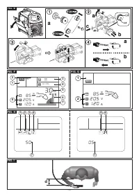
b) selecting 2T or 4T (Fig. H-3 flashing)
The user can select whether to use the 2T or the 4T mode, but only if the spot
welding time is set at “OFF”. Rotate the knob and select the required mode, then
confirm and exit from the menu by pressing the knob.
9. ADVANCED SETTINGS
9.1 Adjustable advanced parameters
The following welding parameters can be personalised, both when working in synergic
and manual mode:
Wire up slope (Fig. H-1)
Use to set the wire starting slope to prevent initial accumulation in the welding seam.
Adjustment from 30 to 100 (start as a % of the running speed).
Electronic reactance (Fig. H-2)
Use to set the welding dynamics according to the material and gas used.
Adjustment from 0 (machine with little reactance) to 5 (machine with great reactance).
Wire burning when welding stops (burn back) (Fig. H-3)
Use to adjust the wire burn back time, optimising the final wire cut to make restarting
welding easier.
Adjustment from 0 to 200 (hundredths of a second).
Post gas (Fig. H-4)
Use to adjust the protective gas output time when welding is finished (Adjustment 0÷5
seconds). This adjustment guarantees weld protection and torch cooling.
9.2 Setting the advanced parameters
To access the parameter adjustment menu press the knobs (Fig. C-1) and (Fig. C-2)
contemporaneously for at least 1 second then release them. Each parameter can
be set at the required value by rotating/pressing the knob (Fig. C-2) (value shown in
(Fig.H-7)) until the exit from the menu.
10. RESTART DEFAULT
The welding machine can be taken back to the factory settings by keeping the two
knobs (Fig.C-1) and (Fig.C-2) pressed during starting operation.
11. ALARM SIGNALS
Reset is automatic when the reason for alarm activation stops.
Alarm messages that can appear on the display:
-
Welding machine thermostatic safeguard intervention. Operation is stopped
until the machine has cooled sufficiently.
- ALL 001: intervention for protection from over/undervoltage. Check the power supply
voltage
- ALL 002: intervention for protection from short-circuit between torch and earth. Make
sure the welding circuit has not short-circuited.
- ALL 003: intervention for protection from overcurrent in the welding circuit. Make
sure the feeder speed and/or welding voltage are not too high.
When the welding machine is switched off, the signal ALL 001 may appear for
a few seconds.
12. MAINTENANCE
WARNING! BEFORE CARRYING OUT MAINTENANCE OPERATIONS
MAKE SURE THE WELDING MACHINE IS SWITCHED OFF AND DISCONNECTED
FROM THE MAIN POWER SUPPLY.
12.1. ROUTINE MAINTENANCE:
ROUTINE MAINTENANCE OPERATIONS CAN BE CARRIED OUT BY THE
OPERATOR.
12.1.1 Torch
- Do not put the torch or its cable on hot pieces; this would cause the insulating
materials to melt, making the torch unusable after a very short time;
- Make regular checks on the gas pipe and connector seals;
- Every time the wire reel is changed, blow out the wire-guide hose using dry
compressed air (max. 5 bar) to make sure it is not damaged;
- Before every use, check the wear and correct assembly of the parts at the end of the
torch: nozzle, contact tip, gas diffuser.
12.1.2 Wire feeder
- Make frequent checks on the state of wear of the wire feeder rollers, regularly
remove the metal dust deposited in the feeder area (rollers and wire-guide infeed
and outfeed).
12.2 EXTRAORDINARY MAINTENANCE
EXTRAORDINARY MAINTENANCE MUST ONLY BE CARRIED OUT BY
TECHNICIANS WHO ARE EXPERT OR QUALIFIED IN THE ELECTRIC-
MECHANICAL FIELD, AND IN FULL RESPECT OF THE IEC/EN 60974-4
TECHNICAL DIRECTIVE.
WARNING! BEFORE REMOVING THE WELDING MACHINE PANELS
AND WORKING INSIDE THE MACHINE MAKE SURE THE WELDING MACHINE
IS SWITCHED OFF AND DISCONNECTED FROM THE MAIN POWER SUPPLY
OUTLET.
If checks are made inside the welding machine while it is live, this may cause
serious electric shock due to direct contact with live parts and/or injury due to
direct contact with moving parts.
- Inspect the welding machine regularly, with a frequency depending on use and the
dustiness of the environment, and remove the dust deposited on the transformer,
reactance and rectifier using a jet of dry compressed air (max. 10 bar).
- Do not direct the jet of compressed air on the electronic boards; these can be
cleaned with a very soft brush or suitable solvents.
- At the same time make sure the electrical connections are tight and check the wiring
for damage to the insulation.
- At the end of these operations re-assemble the panels of the welding machine and
screw the fastening screws right down.
- Never, ever carry out welding operations while the welding machine is open.
- After having carried out maintenance or repairs, restore the connections and wiring
as they were before, making sure they do not come into contact with moving parts or
parts that can reach high temperatures. Tie all the wires as they were before, being
careful to keep the high voltage connections of the primary transformer separate
from the low voltage ones of the secondary transformer.
Use all the original washers and screws when closing the casing.
13. TROUBLESHOOTING
IN CASE OF UNSATISFACTORY FUNCTIONING, BEFORE SERVICING MACHINE
OR REQUESTING ASSISTANCE, CARRY OUT THE FOLLOWING CHECK:
- Check that when general switch is ON the relative lamp is ON. If this is not the case
then the problem is located on the mains (cables, plugs, outlets, fuses, etc.)
- There is no alarm signalling intervention of the thermostat safeguard, over or
undervoltage or short-circuit.
- Check that the nominal intermittance ratio is correct. In case there is a thermal
protection interruption, wait for the machine to cool down, check that the fan is
working properly.
- Check the mains voltage: if the value is too high or too low the welding machine will
be stopped.
- Check that there is no short-circuit at the output of the machine: if this is the case
eliminate the incovenience.
- Check that all connections of the welding circuit are correct, particularly that the
work clamp is well attached to the workpiece, with no interferring material or surface-
coverings (ie. Paint).
- Protective gas must be of appropriate type and quantity.
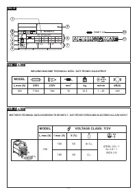
Характеристики

Остались вопросы?Не нашли свой ответ в руководстве или возникли другие проблемы? Задайте свой вопрос в форме ниже с подробным описанием вашей ситуации, чтобы другие люди и специалисты смогли дать на него ответ. Если вы знаете как решить проблему другого человека, пожалуйста, подскажите ему :)


