
Сварочное оборудование BlueWeld Starmig 210 Dual Synergic - инструкция пользователя по применению, эксплуатации и установке на русском языке. Мы надеемся, она поможет вам решить возникшие у вас вопросы при эксплуатации техники.
Если остались вопросы, задайте их в комментариях после инструкции.
"Загружаем инструкцию", означает, что нужно подождать пока файл загрузится и можно будет его читать онлайн. Некоторые инструкции очень большие и время их появления зависит от вашей скорости интернета.

- 6 -
RESIDUAL RISKS
- OVERTURNING: position the welding machine on a horizontal surface that is
able to support the weight: otherwise (e.g. inclined or uneven floors etc.) there
is danger of overturning.
- IMPROPER USE: it is hazardous to use the welding machine for any work
other than that for which it was designed (e.g. de-icing mains water pipes).
- MOVING THE WELDING MACHINE: Always secure the gas bottle, taking
suitable precautions so that it cannot fall accidentally (if used).
- Do not use the handle to hang the welding machine.
The safety guards and moving parts of the covering of the welding machine
and of the wire feeder should be in their proper positions before connecting the
welding machine to the power supply.
WARNING! Any manual operation carried out on the moving parts of the wire
feeder, for example:
- Replacing rollers and/or the wire guide;
- Inserting wire in the rollers;
- Loading the wire reel;
- Cleaning the rollers, the gears and the area underneath them;
- Lubricating the gears.
SHOULD BE CARRIED OUT WITH THE WELDING MACHINE SWITCHED OFF
AND DISCONNECTED FROM THE POWER SUPPLY OUTLET.
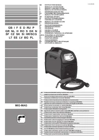
2. INTRODUCTION AND GENERAL DESCRIPTION
This welding machine is a source of current for arc welding, made specifically for MAG
welding carbon steel or weak alloys with CO
2
protective gas or Argon/CO
2
mixes,
using full or core electrode wires.
It is also ideal for MIG welding stainless steel with Argon gas containing + 1-2%
oxygen, aluminium and CuSi
3
, CuAl
8
(brazing) with Argon gas, using electrode wires
that are suitable for the workpiece to be welded.
Suitable core wires can also be used without Flux protection gas, adapting the polarity
of the torch to what is indicated by the wire producer.
SYNERGIC operation guarantees fast and easy welding parameter setting, always
guaranteeing high arc control and welding quality (One Touch Technology).
It is particularly suitable for light metalwork fabrication and in body shops, for welding
galvanized plates, high stress stainless steel and aluminium.
2.1 MAIN CHARACTERISTICS
- Synergic (automatic) or manual operation;
- 17 pre-set synergic curves;
- Wire speed, welding voltage and welding current shown on an LCD screen;
- 2T, 4T and spot operation selection;
- Adjustments: wire up slope, electronic reactance, wire burn-back time, post gas;
- Polarity change for GAS MIG-MAG/BRAZING welding or NO GAS/FLUX;
- Thermostatic safeguard;
- Protection against accidental short-circuits caused by contact between torch and
earth;
- Protection against irregular voltage (power supply voltage too high or too low);
2.2 STANDARD ACCESSORIES
- torch;
- return cable complete with earth clamp.
2.3 OPTIONAL ACCESSORIES
- Argon bottle adapter;
- Trolley;
- Self darkening helmet;
- MIG MAG welding kit.
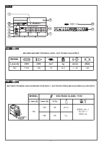
3. TECHNICAL DATA
3.1 DATA PLATE
The most important data regarding use and performance of the welding machine are
summarised on the rating plate and have the following meaning:
Fig. A
1-
EUROPEAN standard of reference, for safety and construction of arc welding
machines.
2-
Symbol for internal structure of the welding machine.
3-
Symbol for welding procedure provided.
4-
Symbol
S
: indicates that welding operations may be carried out in environments
with heightened risk of electric shock (e.g. very close to large metallic volumes).
5-
Symbol for power supply line:
1~ : single phase alternating voltage;
3~ : 3-phase alternating voltage.
6-
Protection rating of the covering.
7-
Technical specifications for power supply line:
-
U
1
: Alternating voltage and power supply frequency of welding machine (allowed
limit ±10%).
-
I
1 max
: Maximum current absorbed by the line.
-
I
1eff
: effective current supplied.
8-
Performance of the welding circuit:
-
U
0
: maximum no-load voltage (open welding circuit).
-
I
2
/U
2
: current and corresponding normalised voltage that the welding machine
can supply during welding.
-
X
: Duty cycle: indicates the time for which the welding machine can supply the
corresponding current (same column). It is expressed as %, based on a 10 min.
cycle (e.g. 60% = 6 minutes working, 4 minutes pause, and so on)
.
If the usage factors (on the plate, referring to a 40°C environment) are exceeded,
the thermal safeguard will trigger (the welding machine will remain in standby
until its temperature returns within the allowed limits).
-
A/V-A/V
: shows the range of adjustment for the welding current (minimum
maximum) at the corresponding arc voltage.
9-
Manufacturer’s serial number for welding machine identification (indispensable for
technical assistance, requesting spare parts, discovering product origin).
10-
: Size of delayed action fuses to be used to protect the power line.
11-
Symbols referring to safety regulations, whose meaning is given in chapter 1
“General safety considerations for arc welding”.
Note: The data plate shown above is an example to give the meaning of the symbols
and numbers; the exact values of technical data for the welding machine in your
possession must be checked directly on the data plate of the welding machine itself.
3.2 OTHER TECHNICAL DATA
- WELDING MACHINE: see table 1 (TAB.1)
- TORCH: see table 2 (TAB.2)
The welding machine weight is shown in table 1 (TAB. 1).
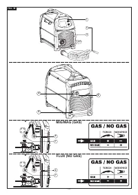
4. DESCRIPTION OF THE WELDING MACHINE
4.1 CONTROL DEVICES: ADJUSTMENT AND CONNECTION.
4.1.1 WELDING MACHINE (Fig. B)
At the front:
1- Control panel (see description).
2- Cable and welding torch.
3- Cable and earth clamp.
At the back:
4- Main ON/OFF switch.
5- Shielding gas hose connector.
6- Power supply cable.
In the reel space:
7- Positive terminal (+).
8- Negative terminal (-).
N.B. Polarity inversion for FLUX welding (no gas).
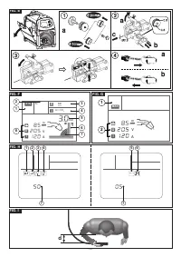
4.1.2 WELDING MACHINE CONTROL PANEL (Fig. C)
1- Adjustment of the welding power (synergic operation) or of the wire feed speed
(manual operation). Press the knob to select either SYNERGIC or MANUAL
operation.
2- Adjustment of the arc length (synergic operation) or of the welding voltage (manual
operation). Press the knob to access the various welding machine settings menu;
3- LCD display.
5. INSTALLATION
WARNING! ALL INSTALLATION OPERATIONS AND ELECTRICAL
CONNECTIONS MUST ALWAYS BE CARRIED OUT WITH THE WELDING
MACHINE SWITCHED OFF AND DISCONNECTED FROM THE POWER SUPPLY.
THE ELECTRIC CONNECTIONS MUST ONLY BE CARRIED OUT BY EXPERT OR
QUALIFIED TECHNICIANS.
Return cable-clamp assembly
Fig. D
5.1 POSITIONING THE WELDING MACHINE
Choose the place where the welding machine is to be installed so that there are no
obstructions to the cooling air inlets and outlets; at the same time make sure that
conductive dust, corrosive vapours, humidity etc. cannot be drawn into the machine.
Leave at least 250 mm of free space all around the welding machine.
WARNING! Position the welding machine on a level surface with
sufficient load-bearing capacity, so that it cannot be tipped over or shift
dangerously.
5.2 CONNECTION TO THE MAIN POWER SUPPLY
- Before making any electrical connection, check the rating plate data on the welding
machine to make sure they correspond to the voltage and frequency of the available
power supply where the machine is to be installed.
- The welding machine must be connected only and exclusively to a power supply with
the neutral conductor connected to earth.
- To guarantee protection against indirect contact use the following types of residual
current devices:
- A type (
) for single-phase machines.
- In order to satisfy the requirements of the EN 61000-3-11 (Flicker) standard we
recommend connecting the welding machine to the interface points of the main
power supply that have an impedance of less than Zmax = 0.25 ohm.
- The IEC/EN 61000-3-12 Standard does not apply to the welding machine.
If the welding machine is connected to an electrical grid, the installer or user must
make sure that the machine can indeed be connected (if necessary, consult the
company that manages the electrical grid).
5.2.1 Plug and outlet
Connect the power supply plug to a mains socket fitted with fuses or an automatic
circuit-breaker; the corresponding earth terminal should be connected to the (yellow-
green) earth conductor of the power supply. Table 1 (TAB. 1) shows the recommended
delayed fuse sizes, in amps, for the main supply, which have been chosen according
to the maximum rated current output from the welding machine, and to the nominal
power supply voltage.
WARNING! Non-compliance with the above regulations renders the
manufacturer’s safety system (class I) inefficient, with resulting serious risks to
people (e.g. electric shock) and things (e.g. fire).
5.3 WELDING CIRCUIT CONNECTIONS
WARNING! BEFORE CARRYING OUT THE FOLLOWING
CONNECTIONS MAKE SURE THAT THE WELDING MACHINE IS SWITCHED OFF
AND DISCONNECTED FROM THE POWER SUPPLY.
Table 1
(TAB. 1)
shows the recommended sizes of the welding cables (in mm
2
),
according to the maximum current output from the welding machine.
Характеристики

Остались вопросы?Не нашли свой ответ в руководстве или возникли другие проблемы? Задайте свой вопрос в форме ниже с подробным описанием вашей ситуации, чтобы другие люди и специалисты смогли дать на него ответ. Если вы знаете как решить проблему другого человека, пожалуйста, подскажите ему :)


