
Сварочное оборудование BlueWeld Starmig 210 Dual Synergic - инструкция пользователя по применению, эксплуатации и установке на русском языке. Мы надеемся, она поможет вам решить возникшие у вас вопросы при эксплуатации техники.
Если остались вопросы, задайте их в комментариях после инструкции.
"Загружаем инструкцию", означает, что нужно подождать пока файл загрузится и можно будет его читать онлайн. Некоторые инструкции очень большие и время их появления зависит от вашей скорости интернета.

- 7 -
5.3.1 Connecting to the gas bottle (if used)
- The gas bottle that can be positioned on the trolley supporting surface: max 30kg.
- Screw the pressure reducer(*) onto the gas bottle, inserting the appropriate adapter
supplied as an accessory when Argon or an Argon/CO
2
mixture is used.
- Connect the gas input hose to the reducer and tighten the clamp.
- Loosen the adjustment ring nut on the pressure reducing valve before opening the
gas bottle valve.
(*) Accessory to be purchased separately if not supplied with the product.
5.3.2 Connecting the welding current return cable
Must be connected to the workpiece or to the metal bench on which it is positioned,
keeping it as close as possible to the joint being done.
5.3.3 Torch
Prepare the torch when loading the wire for the first time, by dismantling the nozzle
and the contact tip, to ease its exit.
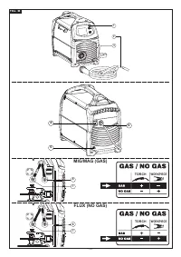
5.3.4 Polarity change
Fig. B
- Open the reel area door.
- MIG/MAG welding (gas):
- Connect the torch cable to the red clamp (+).
- Connect the clamp return cable to the black clamp (-).
- FLUX welding (no gas):
- Connect the torch cable to the black clamp (-).
- Connect the clamp return cable to the red clamp (+).
- Close the reel area door.
5.3.5 Recommendations:
- Screw the welding cable connectors right down into the quick couplings (if present),
so as to ensure perfect electrical contact; otherwise, the connectors will overheat,
wear rapidly and become inefficient.
- Use welding cables that are as short as possible.
- Do not use metal structures that are not part of the workpiece to substitute the welding
current return cable; this could endanger safety and produce an unsatisfactory weld.
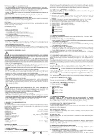
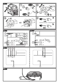
5.4 LOADING THE WIRE REEL (Fig. E)
WARNING! BEFORE STARTING THE OPERATIONS TO LOAD THE WIRE
MAKE SURE THE WELDING MACHINE IS SWITCHED OFF AND DISCONNECTED
FROM THE MAIN POWER SUPPLY OUTLET.
MAKE SURE THAT THE WIRE FEEDER ROLLERS, THE WIRE GUIDE HOSE AND
THE CONTACT TIP OF THE TORCH MATCH THE DIAMETER AND TYPE OF WIRE
TO BE USED AND MAKE SURE THAT THESE ARE FITTED CORRECTLY. WHEN
INSERTING AND THREADING THE WIRE DO NOT WEAR PROTECTIVE GLOVES.
- Open the reel compartment door.
- Position the wire reel on the spindle, holding the end of the wire upwards; make sure
the tab for pulling the spindle is correctly seated in its hole
(1a)
.
- Release the pressure counter-roller(s) and move them away from the lower roller(s)
(2a)
;
- Make sure that the towing roller(s) is suited to the wire used
(2b)
.
- Free the end of the wire and remove the distorted end with a clean cut and no burr;
turn the reel anti-clockwise and thread the end of the wire into the wire-guide infeed,
pushing it 50-100mm into the wire guide of the torch fitting
(2c)
.
- Re-position the counter-roller(s), adjusting the pressure to an intermediate value,
and make sure that the wire is correctly positioned in the groove of the lower roller(s)
(3)
- Remove the nozzle and contact tip
(4a)
.
- Insert the welding machine plug in the power supply outlet, switch on the welding
machine, press the torch button and wait for the end of the wire to pass through the
whole of the wire guide hose and protrude by 10-15 cm from the front part of the
torch, release the button.
WARNING! During these operations the wire is live and subject to
mechanical stress; therefore if adequate precautions are not taken the wire
could cause hazardous electric shock, injury and striking of electric arcs:
- Do not direct the mouthpiece of the torch towards parts of the body.
- Keep the torch away from the gas bottle.
- Re-fit the contact tip and the nozzle onto the torch
(4b)
.
- Check that wire feed is regular; set the roller and spindle braking pressure to the
minimum possible values making sure that the wire does not slide in the groove and
when feed is halted the loops of wire are not loosened by excessive reel inertia.
- Cut the end of the wire so that 10-15 mm protrude from the nozzle.
- Close the reel compartment door.
6. WELDING: PROCESS DESCRIPTION
6.1 SHORT ARC
The wire melts and the weld bead detaches because the wire tip in the weld pool short-
circuits (up to 200 times per second). The free length of the wire (stick-out) is normally
between 5 and 12 mm.
Carbon steel and low-alloys
- Usable wire diameter:
0.6 - 0.8 - 1.0 mm
- Usable gas:
CO
2
or Ar/CO
2
mixes
Stainless steel
- Usable wire diameter:
0.8 - 1.0 mm
- Usable gas:
Ar/O
2
or Ar/CO
2
(1-2%) mixes
Aluminium and CuSi/CuAl
- Usable wire diameter:
0.8 - 1.0 mm
- Usable gas:
Ar
Core wire
- Usable wire diameter:
0.8 - 0.9 - 1.2 mm
- Usable gas:
None
6.2 PROTECTIVE GAS
The protective gas flow rate must be 8-14 l/min.
7. OPERATION MODE
7.1 Operation in SYNERGIC mode
When the parameters such as material, wire diameter
, gas type
have been
defined by the user, the welding machine sets itself automatically in the best operation
conditions established by the different synergy curves that are saved. The user only
has to select the material thickness to begin welding (OneTouch Technology).
7.1.1 LCD display in SYNERGIC mode (Fig. F)
N.B.: All the values that are shown and that can be selected depend on the type of
welding selected previously.
1- Synergy operation mode
;
2- Material to be welded. Types available: Fe (steel), SS (stainless steel), Al
(aluminium), CuSi/CuAl (galvanized plate - brazing), Flux (cored wire - NO GAS
welding);
3- Diameter of the wire to be used. Values available: 0.6 - 0.8 - 0.9 - 1 - 1.2 mm;
4- Recommended protective gas. Types available: Ar/CO
2
, CO
2
, Ar, Ar/O
2
;
5- Thickness of the material to be welded. Values available from 0 to 5 mm;
6- Graphic indicator of the material thickness
7- Graphic indicator of the welding seam shape;
8- Welding values;
wire feed speed;
welding voltage;
welding current;
7.1.2 Setting the parameters
To access the parameter adjustment menu press the knob (Fig. C-2) for at least 1
second then release it:
a) material selection (Fig. F-2 material flashing)
- rotate the knob (Fig. C-2) to select the required material and confirm by pressing
and releasing the same knob;
b) wire diameter selection (Fig. F-3 wire diameter flashing)
- rotate the knob (Fig. C-2) to select the required material and confirm by pressing
and releasing the same knob;
c) gas selection (Fig. F-4 gas type flashing)
- rotate the knob (Fig. C-2) or directly select the proposed gas and confirm by
pressing and releasing the knob; this allows exiting from the parameter settings
menu and the display on the monitor of the pre-set values.
After having defined with the knob (Fig. C-1) the material thickness (Fig. F-5) the user
can start welding.
7.1.3 Adjusting the welding seam shape
The shape of the welding seam can be adjusted using the knob (Fig. C-2) which
adjusts the arc length, therefore establishing the higher or lower temperature for
welding.
The adjustment scale ranges from -9 ÷ 0 ÷ +9; in most cases the optimal basic setting
is given (the value is shown on the LCD display to the left of the graphic signal showing
the welding seam and disappears after a set time) when the knob is in the intermediate
position (0
).
Using the knob (Fig. C-2) the graphic indication on the display of the welding seam
changes, showing a more convex, flatter or more concave result.
Convex shape.
It means that there is a low thermal supply therefore welding is
“cold”, with little penetration; rotate the knob clockwise for greater thermal supply to
weld with higher fusion.
Concave shape.
It means there is a high thermal supply therefore welding is too
“hot”, with excessive penetration; rotate the knob counter-clockwise for lower fusion.
7.2 Operation in MANUAL mode
The user can personalise all the welding parameters.
7.2.1 LCD display in SYNERGIC mode (Fig. F)
1- Manual operation mode
;
2- Welding values;
wire feed speed;
welding voltage;
welding current;
7.2.2 Setting the parameters
In manual mode, the wire feeding speed and the welding voltage are adjusted
separately. The knob (Fig. C-1) adjusts the wire speed, the knob (Fig. C-2) adjusts
the welding voltage (which determines the welding power and influences the seam
shape). The welding current is shown on the display only during welding.
8. CONTROLLING THE TORCH PUSH-BUTTON
8.1 Torch push-button control mode
3 different torch push-button control modes can be set, which remain valid with both
synergic and manual operation:
Spot welding mode (Fig. H-5)
Use for MIG/MAG spot welding with control of welding duration (when at OFF
excluded; 0.1÷5 seconds).
2T mode (Fig. H6)
Welding begins when the torch push-button is pressed and ends when the push-
button is released.
4T mode (Fig. H6)
Welding begins when the torch push-button is pressed and released, and ends only
when the torch push-button is pressed and released a second time. This mode is
useful for long welding operations.
8.2 Setting the torch push-button control mode
To access the parameter adjustment menu press the knob (Fig. C-2) for at least 3
second then release it:
a) spot welding time adjustment (Fig. H-2 flashing)
- rotate the knob (Fig. C-2) to select the required time or select “OFF” to disable the
function; confirm by pressing and releasing the same knob.
If the spot welding time is set at a value of between 0.1-5 sec., the “2T/4T” modes
Характеристики

Остались вопросы?Не нашли свой ответ в руководстве или возникли другие проблемы? Задайте свой вопрос в форме ниже с подробным описанием вашей ситуации, чтобы другие люди и специалисты смогли дать на него ответ. Если вы знаете как решить проблему другого человека, пожалуйста, подскажите ему :)


