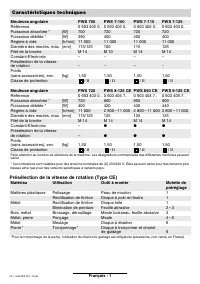
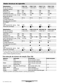
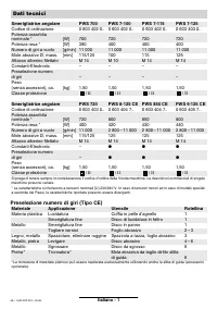
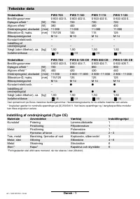
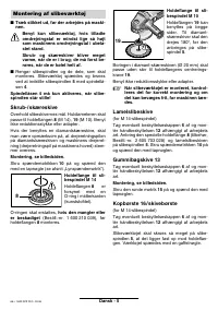
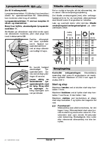
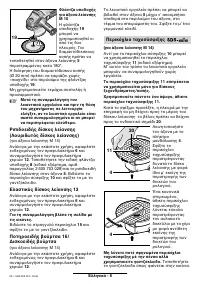
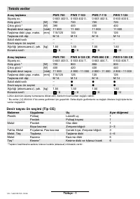
Шлифмашины Bosch PWS 8 125 CE - инструкция пользователя по применению, эксплуатации и установке на русском языке. Мы надеемся, она поможет вам решить возникшие у вас вопросы при эксплуатации техники.
Если остались вопросы, задайте их в комментариях после инструкции.
"Загружаем инструкцию", означает, что нужно подождать пока файл загрузится и можно будет его читать онлайн. Некоторые инструкции очень большие и время их появления зависит от вашей скорости интернета.


English - 5
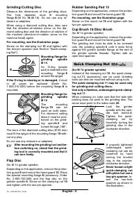
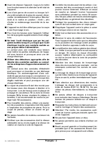
Grinding / Cutting Disc
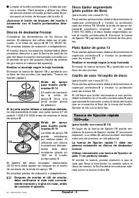
Observe the dimensions of the grinding discs.
The hole diameter must fit mounting
flange 8 (M 14), 19 (M 10). Do not use any re-
ducers or adapters.
When using a diamond cutting disc, take care
that the direction-of-rotation arrow on the dia-
mond cutting disc and the direction of rotation of
the machine (direction-of-rotation arrow on the
machine head) agree.
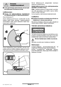
For mounting, see the illustration page.
Screw on the clamping nut 10 and tighten with
the two-pin spanner (see Section “Quick-clamp-
ing Nut”).
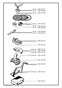
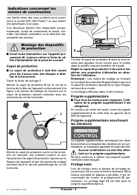
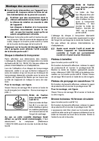
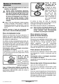
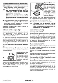
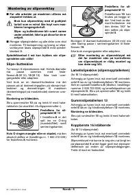
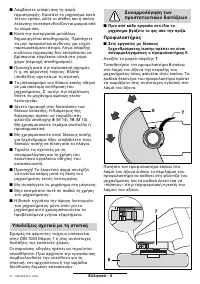
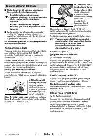
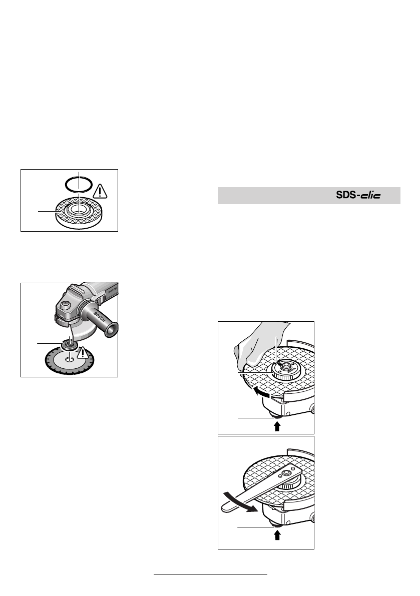
Mounting flange for
grinding spindle
M 14
An O-ring (plastic
part) is inserted in the
mounting flange 8
around the spigot.
If the O-ring is missing or is damaged, it must
in all cases be replaced (Order No.
1 600 210 039) before the mounting flange 8 is
mounted.
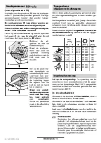
Mounting flange for
grinding spindle
M 10
The mounting
flange 19 can be
used on both sides.
For diamond cutting
discs it must be posi-
tioned on the grind-
ing spindle 5 and
turned through 180°.
The bore of the diamond cutting disc (Ø 20 mm)
must fit the spigot of the mounting flange 19 with-
out any play.
Do not use any reducers or adapters.
☞
After mounting the grinding tool and be-
fore switching on, check that the grind-
ing tool is correctly mounted and that it
can turn freely.
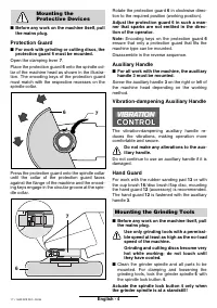
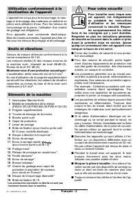
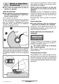
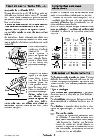
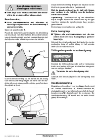
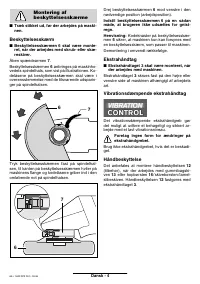
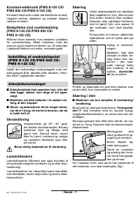
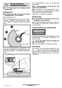
Flap Disc
(for M 14 grinder spindle)
Depending on the application, remove the protec-
tion guard 6 and mount the hand guard 12. Place
the special mounting flange 8 (accessory, Order
No. 2 605 703 028) and the flap disc on the
grinder spindle 5. Screw on the clamping nut 10
and tighten with the two-pin spanner.
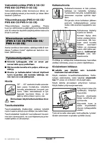
Rubber Sanding Pad 13
Depending on the application, remove the protec-
tion guard 6 and mount the hand guard 12.
For mounting, see the illustration page.
Screw on the round nut 15 and tighten with the
two-pin spanner.
Cup Brush 16 / Disc Brush
(for M 14 grinder spindle)
Depending on the application, remove the protec-
tion guard 6 and mount the hand guard 12.
The grinding tool must be able to be screwed
onto the grinding spindle 5 until it rests firmly
against the grinder spindle flange at the end of
the grinder spindle threads. Tighten with an
open-end spanner.
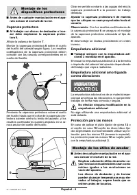
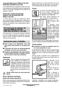
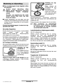
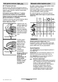
(for M 14 grinder spindle)
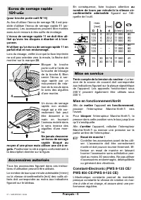
Instead of the clamping nut 10, the quick-clamp-
ing nut 11 (accessory) can be used. Grinding
tools can then be mounted without using tools.
The quick-clamping nut 11 may be used only
for grinding and cutting discs.
Use only a flawless, undamaged quick-clamp-
ing nut 11.
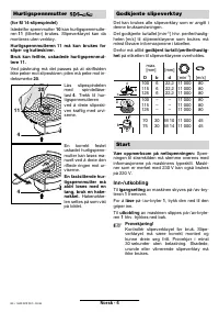
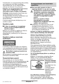
When screwing on, take care that the side with
printing does not point to the grinding disc. The
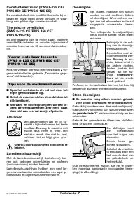
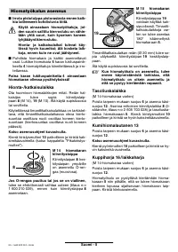
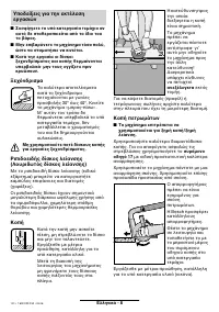
arrow must point to the index mark 20.
Lock the grinder
spindle with the spin-
dle lock button 4.
Tighten the quick-
clamping nut by
forcefully turning the
grinding disc in the
clockwise direction.
A properly tightened
undamaged, quick-
clamping nut can be
loosened by hand
turning the knurled
ring in the counter-
clockwise direction.
Never loosen a tight
quick-clamping nut
with pliers but use a
two-pin spanner. In-
sert the two-hole
spanner as shown in
the illustration.
8
19
Quick Clamping Nut
4
20
11
4
18 • 1 609 929 F32 • 03.06


