
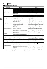
Мойки высокого давления Makita HW 140 - инструкция пользователя по применению, эксплуатации и установке на русском языке. Мы надеемся, она поможет вам решить возникшие у вас вопросы при эксплуатации техники.
Если остались вопросы, задайте их в комментариях после инструкции.
"Загружаем инструкцию", означает, что нужно подождать пока файл загрузится и можно будет его читать онлайн. Некоторые инструкции очень большие и время их появления зависит от вашей скорости интернета.


13
English
EN
3
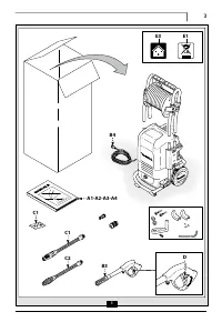
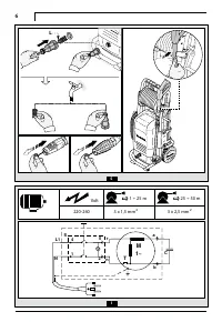
GENERAL INFORMATION FIG.1
3.1 Use of the manual
This manual forms an integral part of the appliance and should be
kept for future reference. Please read it carefully before installing/
using the unit. If the appliance is sold, the Seller must pass on this
manual to the new owner along with the appliance.
3.2 Delivery
The appliance is delivered partially assembled in a cardboard box.
The supply package is illustrated in fig.1.
3.2.1
Documentation supplied with the appliance
A1
Use and maintenance manual
A2
Safety
instructions
A3
Declaration of conformity
A4
Warranty
regulations
3.3 Disposing of packaging
The packaging materials are not environmental pollutants but must
still be recycled or disposed of in compliance with the relevant
legislation in the country of use.
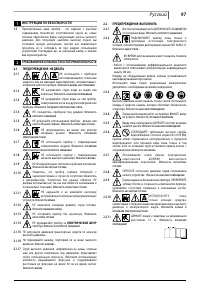
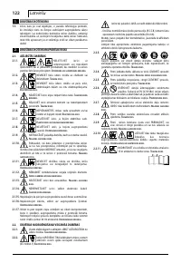
3.4 Safety
signs
Comply with the instructions provided by the safety signs fitted to
the appliance.
Check that they are present and legible; otherwise, fit replacements
in the original positions.
E1 sign – Indicates that the appliance
must not be disposed of
as
municipal waste; it may be handed in to the dealer on purchase of a
new appliance. The appliance's electrical and electronic parts must
not be reused for improper uses since they contain substances
which constitute health hazards.
3.4.1 Symbols
E2 symbol – Indicates that the appliance is intend-
ed for professional use, i.e. for experienced people
informed about the relative technical, regulatory
and legislative aspects and capable of performing the
operations necessary for the use and maintenance of the
appliance.
E3 symbol – Indicates that the appliance is
intended for non-professional (domestic) use.
4
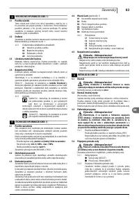
TECHNICAL INFORMATION FIG.1
4.1 Envisaged
use
This appliance has been designed for individual use for the cleaning
of vehicles, machines, boats, masonry, etc, to remove stubborn dirt
using clean water and biodegradable chemical detergents.
Vehicle engines may be washed only if the dirty water is disposed of
as per regulations in force.
- Intake water temperature:
see data plate on the appliance
.
- Intake water pressure:
min. 0,1MPa-max 1MPa.
- Operating ambient temperature:
above 0°C
.
The appliance is compliant with the EN 60335-2-79/A1 standard.
4.2 Operator
The symbol on the front cover identifies the appliance’s intended
operator (professional or non-professional).
4.3 Improper
use
Use by unskilled persons or those who have not read and under-
stood the instructions in the manual is forbidden.
The introduction of inflammable, explosive and toxic liquids into the
appliance is prohibited.
Use of the appliance in a potentially inflammable or explosive
atmosphere is forbidden.
The use of non-original spare parts and any other spare parts not
specifically intended for the model in question is prohibited.
All modifications to the appliance are prohibited. Any modifications
made to the appliance shall render the Declaration of Conformity
null and void and relieve the manufacturer of all liability under civil
and criminal law.
4.4 Main
components
(see fig.1)
B1
Adjustable spray nozzle
B2
Lance
B3
Gun with safety catch
B4
Power supply cable with plug
B5
High pressure hose
B6
Detergent
tank
4.4.1 Accessories
C1
Nozzle cleaning tool
C2
Rotating nozzle kit
C3
Handle
C4
Brush (on models with this feature)
C5
Hose reel (on models with this feature)
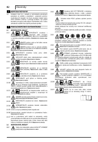
4.5 Safety
devices
Caution - Danger!
Do not tamper with or adjust the safety valve setting.
- Safety valve and/or pressure limiting valve.
The safety valve is also a pressure limiting valve.
When the gun trigger is released, the valve opens and the water
recirculates through the pump inlet.
- Safety catch (
D
): prevents accidental spraying of water.
5
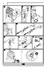
INSTALLATION FIG.2
5.1 Assembly
Caution - Danger!
All installation and assembly operations must be
performed with the appliance disconnected from the mains
power supply.
The assembly sequence is illustrated in
fig.2
.
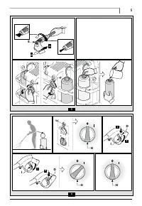
5.2 Assembling the rotating nozzle
(For models with this feature)
The rotating nozzle kit delivers greater washing power.
Use of the rotating nozzle may cause of reduction in pressure of
25% compared to the pressure obtained with the adjustable nozzle.
However, the rotating nozzle kit delivers greater washing power due
to the rotation of the water jet.
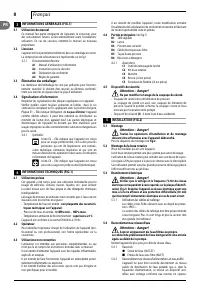
5.3 Electrical
connection
Caution - Danger!
Check that the electrical supply voltage and frequen-
cy (V-Hz) correspond to those specified on the appliance
data plate (fig.2). The appliance should only be connected
to a mains power supply equipped with an adequate earth
connection and a differential security breaker (30 mA) to cut
off the electricity supply in the instance of a short circuit.
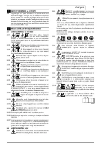
5.3.1
Use of extension cables
Use cables and plugs featuring “IPX5” protection level.
The cross-section of the extension cable should be pro-
portionate to its length; the longer it is, the greater its
cross-section should be. See table I.
5.4 Water supply connection
Caution - Danger!
Only clean or filtered water should be used for intake.
The delivery of the water intake tap should be equal to that
of pump capacity.
Place the appliance as close to the water supply system as possible.
5.4.1 Connection
points
●
Water outlet (OUTLET)
■
Water inlet with filter (INLET)
5.4.2
Connection to the mains water supply
The appliance can be connected directly to the mains
drinking water supply only if the supply hose is fitted with
a backflow preventer valve as per current regulations in
force. Make sure that the hose is at least Ø 13 mm and
that it is reinforced.


