Материнские платы GIGABYTE GA H67A USB3 B3 rev 1 0 - инструкция пользователя по применению, эксплуатации и установке на русском языке. Мы надеемся, она поможет вам решить возникшие у вас вопросы при эксплуатации техники.
Если остались вопросы, задайте их в комментариях после инструкции.
"Загружаем инструкцию", означает, что нужно подождать пока файл загрузится и можно будет его читать онлайн. Некоторые инструкции очень большие и время их появления зависит от вашей скорости интернета.


Hardware Installation
- 24 -
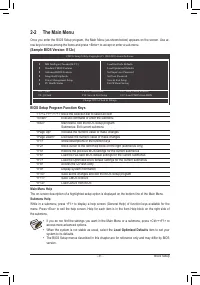
•
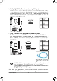
A RAID 0 or RAID 1 configuration requires at least two hard drives. If more than two hard
drives are to be used, the total number of hard drives must be an even number.
•
A RAID 5 configuration requires at least three hard drives. (The total number of hard drives
does not have to be an even number.)
•
A RAID 10 configuration requires four hard drives.
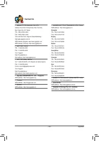
7) SATA3_0/1 (SATA 6Gb/s Connectors, Controlled by H67 Chipset)
The SATA connectors conform to SATA 6Gb/s standard and are compatible with SATA 3Gb/s and SATA
1.5Gb/s standard. Each SATA connector supports a single SATA device. The SATA3_0 and SATA3_1
connectors support RAID 0 and RAID 1. RAID 5 and RAID 10 can be implemented on the two connec-
tors with the SATA2_2/3/4/5 connector
(Note)
. Refer to Chapter 5, "Configuring SATA Hard Drive(s)," for
instructions on configuring a RAID array.
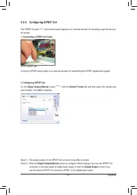
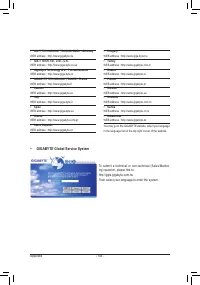
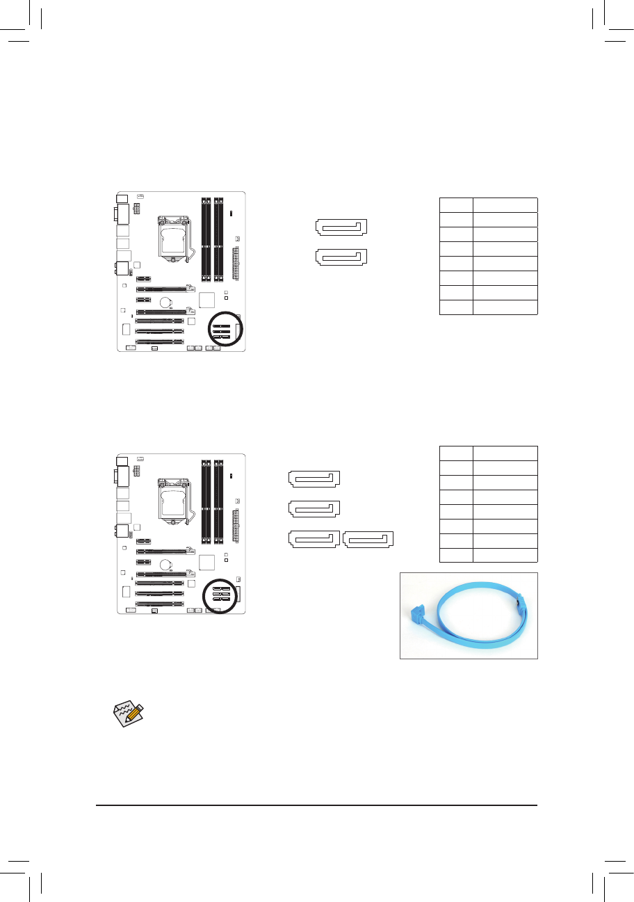
Please connect the L-shaped end of
the SATA cable to your SATA hard
drive.
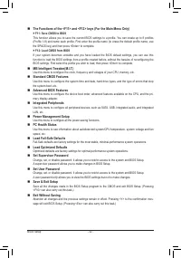
8) SATA2_2/3/4/5 (SATA 3Gb/s Connectors, Controlled by H67 Chipset)
The SATA connectors conform to SATA 3Gb/s standard and are compatible with SATA 1.5Gb/s standard.
Each SATA connector supports a single SATA device. The H67 Chipset supports RAID 0, RAID 1,
RAID 5, and RAID 10. Refer to Chapter 5, "Configuring SATA Hard Drive(s)," for instructions on configur
-
ing a RAID array.
(Note) When a RAID set is built across the SATA 6Gb/s and SATA 3Gb/s channels, the system perfor-
mance of the RAID set may vary depending on the devices being connected.
1
1
7
7
DEBUG
PORT
G.QBOFM
DEBUG
PORT
G.QBOFM
SATA3_0
SATA3_1
1
1
1
DEBUG
PORT
G.QBOFM
DEBUG
PORT
G.QBOFM
DEBUG
PORT
G.QBOFM
SATA2_3
SATA2_4
SATA2_5
7
7
DEBUG
PORT
G.QBOFM
SATA2_2
7
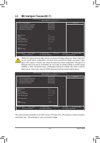
Pin No.
Definition
1
GND
2
TXP
3
TXN
4
GND
5
RXN
6
RXP
7
GND
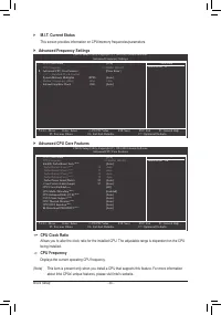
Pin No.
Definition
1
GND
2
TXP
3
TXN
4
GND
5
RXN
6
RXP
7
GND


