Котел Baxi BPI Eco 1.550 / 1.650 - инструкция пользователя по применению, эксплуатации и установке на русском языке. Мы надеемся, она поможет вам решить возникшие у вас вопросы при эксплуатации техники.
Если остались вопросы, задайте их в комментариях после инструкции.
"Загружаем инструкцию", означает, что нужно подождать пока файл загрузится и можно будет его читать онлайн. Некоторые инструкции очень большие и время их появления зависит от вашей скорости интернета.


34
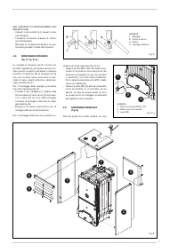
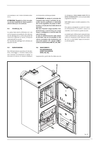
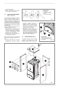
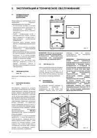
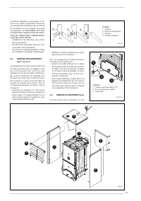
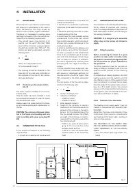
support brackets.
The assembly of the casing components
must be carried out in the following way:
– U n s c r e w w i t h s o m e r o t a t i o n s t h e
second or third nut of each tie rod.
– Connect the lef t side (1) on the lower
and upper tie rod of the boiler and adjust
the position of the nut and lock-nut of the
upper tie-rod.
– Block the side by tightening the locknuts.
– In order to assembly the right side (2)
proceed in the same way.
– Connect the rear panel (4) introducing
the two splines in the vents obtained on
each side and lock it with self-threading
screws.
– The protection deflector (5) is fixed to
t h e c o n t r o l p a n e l ( 6 ) w i t h t hr e e s e l f -
t hr eading scr ew s. Inser t t he miner al
wool between the two components.
– Fasten the front panel (6) using the pres-
sure pins.
– Unwind the capillary of the thermometer
(7) and and introduce it in the lef t sheath
of the rear head introducing the contact
spring which must be cut at about 45
mm. The thermomet er cable mus t be
placed above the insulation and must not
contact directly the iron cast body.
– Fasten the cover (8) to the sides of the
boiler using the pressure pins.
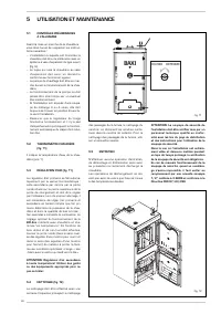
- A p p l y t h e B O I L E R T E C H N I C A L DATA
adhesive plate on the right or lef t side of
the covering, so as to be legible when
the appliance is installed.
N O T I C E : S t o r e t h e " Te s t r e p o r t " a n d
"Declaration of conformity" placed in the
combustion chamber together with the
documents of the boiler.
4.6
DRAUGHT REGULATOR WITH
THERMOSTATIC OPERATION
By means of t he draught r egulat or wit h
thermostatic operation, a continuous varia-
bility of the air introduced in the boiler fur-
nace can be obtained.
By means of a connecting chainle t, t his
r egulat or acts on t he lower pr imar y air
intake port.
Once the set temperature has been rea-
ched, the regulator decreases the opening
of the air intake por t automatically, so to
slow down t he combus tion and pr event
over-heating. In order to optimise the com-
bus tion on t he upper load por t, place a
round adjusting por t that distributes the
secondary air countercurrent compared to
the path of the combustion products.
This pr ocess fur ther incr eases the yield
and allows exploiting the combustion more
effectively. Two types of thermostatic regu-
lators can be assembled on the boilers.
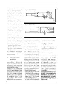
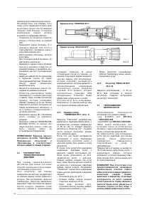
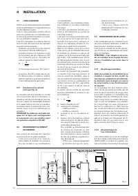
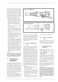
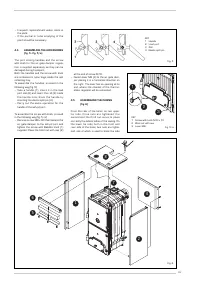
4.6.1
“THERMOMAT RT-C” Regulator
(fig. 7)
The “Thermomat” regulator is equipped
with a thermosetting resin knob of an adju-
stment field from 30 to 100 °C.
Screw the regulator on the 3/4” opening of
the anterior head and orientate the red
index on the upper part.
The lever with the chainlet should be intro-
duced in the regulator holder af ter having
assembled the instrument holder board
and af ter having removed the plastic lock.
If the joint is taken out, which fixes the lever
with the chainlet, take care in assembling it
again in the same position.
Af ter having placed the knob at 60°C, block
the lever with the chainlet in a slightly incli-
ned position downwards, so that the chain-
let will be in axis with the air gate damper.
For the adjustment of the “Thermomat”,
which essentially consists in the determina-
tion of the chainlet length, proceed in the fol-
lowing way:
– Place the knob at 60°C.
– Switch on the boiler with opened air gate
damper.
– When the water temperature of 60° C
is reached in the boiler, fix the chainlet in
such a way on the lever of the air gate
damper, in order to obtain an opening of
about 1 mm.
– Now the regulator is calibrated and it is
possible to choose the desired operating
temperature by rotating the knob.
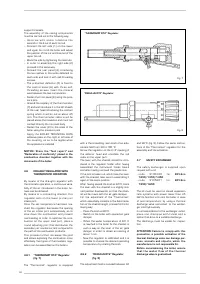
4.6.2
“REGULUS RT2” Regulator
(fig. 8)
The adjustment field is included between 30
and 90°C (fig. 8). Follow the same instruc-
tions of the “Thermomat” regulator for the
assembly and the activation.
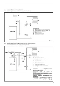
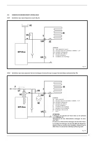
4.7
SAFETY EXCHANGER
T h e s a f e t y e x c h a n g e r i s s u p p l i e d u p o n
request with a kit:
- c o d e 810 5 2 0 0 f o r
B P I - E c o
1.250/1.350/1.450
-
c o d e 810 5 2 01 f o r
B P I - E c o
1.550/1.650
.
The kit must be used on closed expansion
t ank sys t ems with power lower than 35
kW. Its function is to cool the boiler in case
of over -t emperature, by using a thermal
discharge valve connected to the exchan-
ger inlet hydraulically.
In correspondence to the exchanger outlet,
p l a c e o n e d r a i n p i p e w i t h f u n n e l a n d a
siphon that drive to a suitable discharge.
The discharge must be visible for inspec-
tion.
ATTENTION: Failure to comply with this
precaution, a possible activation of the
thermal discharge valve can damage per-
s o n s , a n i m a l s a n d o b j e c t s , w h i c h t h e
manufacturer is not responsible for.
Before commissioning the boiler, ensure
t h a t t h e w a t e r f l o w o f t h e t h e r m a l
discharge valve is guaranteed.
Fig. 8
“REGULUS RT2” Regulator
Fig. 7
“THERMOMAT RT-C” Regulator


