Котел Baxi BPI Eco 1.550 / 1.650 - инструкция пользователя по применению, эксплуатации и установке на русском языке. Мы надеемся, она поможет вам решить возникшие у вас вопросы при эксплуатации техники.
Если остались вопросы, задайте их в комментариях после инструкции.
"Загружаем инструкцию", означает, что нужно подождать пока файл загрузится и можно будет его читать онлайн. Некоторые инструкции очень большие и время их появления зависит от вашей скорости интернета.


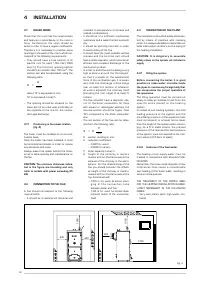


– Frequent replenishment water inlets in
the plant.
– If t he par tial or t o t al emp tying of t he
plant should be necessary.
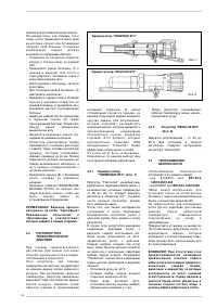
4.4
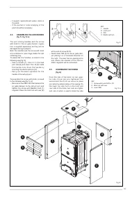
ASSEMBLING THE ACCESSORIES
(fig. 5 - fig. 5/a)
The por t closing handles and t he scr ew
with knob for the air gate damper regula-
tion is supplied separately, as they can be
damaged during transport.
Both the handles and the screw with knob
are contained in nylon bags inside the ash
collecting tray.
To assemble the handles, proceed in the
following way (fig. 5):
– Take a handle (1), inser t it in the load
port slot (2) and insert the roll (3) inside
t h e h a n d l e h o l e ; b l o c k t h e h a n d l e b y
inserting the elastic split pin (4).
– Carr y out t he same operation for t he
handle of the ash-pit port.
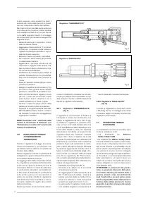
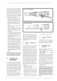
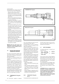
To assemble the screw with knob, proceed
in the following way (fig. 5/a):
– Remove screw M8 x 60 that fastens the
air gate damper to the ash-pit port and
tighten the screw with Bakelite knob (1)
supplied. Place the blind nut with cap (2)
at the end of screw M 10.
– Fasten lever M6 (3) to the air gate dam-
per placing it in a horizontal direction on
the right. The lever has an opening at its
end, where the chainlet of the thermo-
static regulator will be connected.
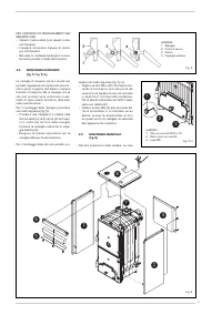
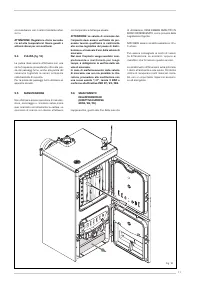
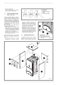
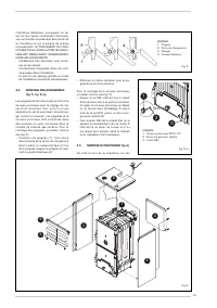
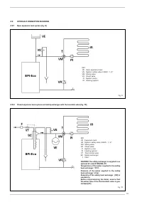
4.5
ASSEMBLING THE CASING
(fig. 6)
From the rear of the boiler, on two upper
t i e r o d s , t h r e e n u t s a r e t i g h t e n e d : t h e
second and the thir d nut ser ve t o place
correctly the lateral sides of the casing. On
the lower tie rods, both in the front and
rear side of the boiler, two nuts are tighte-
ned, one of which is used to block the side
6
5
1
7
4
2
8
Fig. 6
33
KEY
1 Handle
2 Load port
3 Roll
4 Elastic split pin
Fig. 5
1
2
3
KEY
1 Screw with knob M10 x 70
2 Blind nut with cap
3 Lever M6
Fig. 5/a


