
Холодильник Liebherr CN 3503 NoFrost - инструкция пользователя по применению, эксплуатации и установке на русском языке. Мы надеемся, она поможет вам решить возникшие у вас вопросы при эксплуатации техники.
Если остались вопросы, задайте их в комментариях после инструкции.
"Загружаем инструкцию", означает, что нужно подождать пока файл загрузится и можно будет его читать онлайн. Некоторые инструкции очень большие и время их появления зависит от вашей скорости интернета.
u
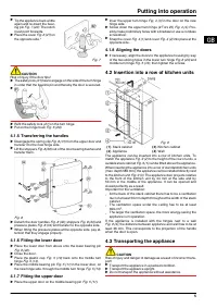
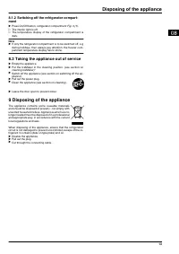
Tip the appliance back a little
again and re-insert the bear-
ing pin
Fig. 7 (22). The notch
must point forwards.
u
Place the cover
Fig. 6 (27) on
the opposite side.*
Fig. 7
CAUTION
Risk of injury if the door tips!
u
The safety lock
(21) has to engage on the side of the turn hinge
in order that the bearing pin and thereby the door is secured.
u
u
Refit the safety lock
(21) on the turn hinge.
u
Put on the hinge bush
Fig. 6 (20).
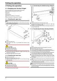
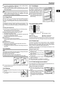
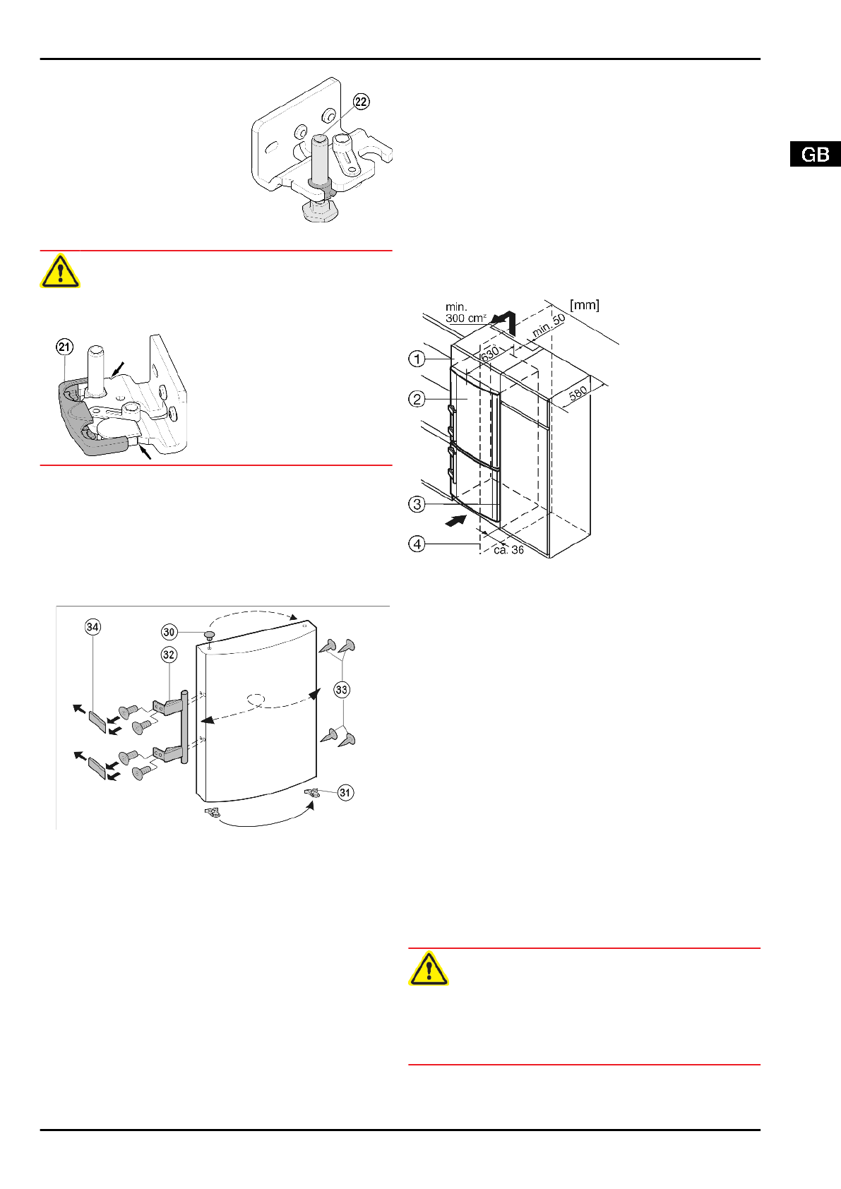
4.1.5 Transferring the handles
u
Disengage the spring clip
Fig. 8 (31) from the upper door and
transfer it to the new hinge side.
u
Lift the stoppers
Fig. 8 (30) out of the door bearing bushes and
transfer them.
Fig. 8
u
Detach the door handles
Fig. 8 (32), stoppers Fig. 8 (33) and
pressure plates
Fig. 8 (34) and transfer to the opposite side.
u
When fitting the pressure plates at the opposite side, pay at-
tention that they engage properly.
4.1.6 Fitting the lower door
u
Place the lower door from above onto the lower bearing pin
Fig. 6 (22).
u
Close the door.
u
Place the plastic cap
Fig. 5 (10) back onto the middle turn
hinge
Fig. 5 (13).
u
Place the middle bearing pin
Fig. 5 (11) in the lower door, on
the new hinge side, through the middle turn hinge
Fig. 5 (13).
4.1.7 Fitting the upper door
u
Place the upper door on the middle bearing pin
Fig. 5 (11).
u
Inser the upper turn hinge
Fig. 4 (3) in the door on the new
hinge side.
u
Screw down the upper turn hinge (2 Torx 25)
Fig. 4 (4). Pos-
sibly make preliminary holes with a bradawl or use a cordless
screwdriver.
u
Snap the cover
Fig. 4 (1) and cover Fig. 4 (2) into place at the
opposite side.
4.1.8 Aligning the doors
u
If necessary, align the doors to the appliance housing by way
of the two oblong holes in the lower turn hinge
Fig. 6 (23) and
middle turn hinge
Fig. 5 (13), then tighten the screws.
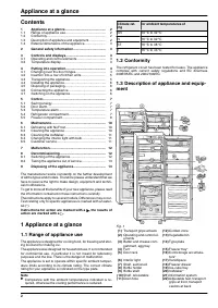
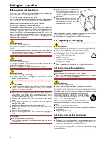
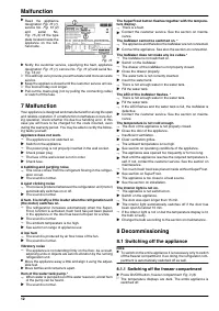
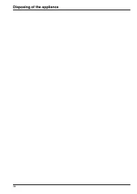
4.2 Insertion into a row of kitchen units
Fig. 9
(1) Stack cabinet
(3) Kitchen cabinet
(2) Appliance
(4) Wall
The appliance can be inserted into a row of kitchen units. To
match the appliance
Fig. 9 (2) to the height of the row of units, a
suitable stack cabinet
Fig. 9 (1) can be fitted above the appliance.
When inserting the appliance into a row of standard kitchen units
(max. depth 580 mm), the appliance can be installed directly next
to the kitchen unit
Fig. 9 (3). The appliance door projects relative
to the front of the kitchen unit by 34 mm at the side and by
50 mm in the middle of the appliance. It can be opened and
closed perfectly as a result.
Important for the ventilation:
-
At the back of the stack cabinet there has to be a ventilation
duct of at least 50 mm depth throughout the width of the stack
cabinet.
-
The ventilation space under the ceiling has to be at least
300 cm
2
.
-
The larger the ventilation space, the more energy-saving the
appliance is in operation.
If the appliance is installed with the hinges next to a wall
Fig. 9 (4), the distance between appliance and wall has to be at
least 36 mm. This corresponds to the projection of the handle
when the door is open.
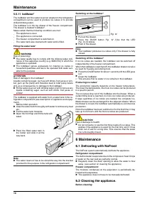
4.3 Transporting the appliance
CAUTION
Risk of injury and danger of damage as a result of incorrect trans-
port!
u
Transport the appliance in a packed condition.
u
Transport the appliance upright.
u
Do not transport the appliance without assistance.
Putting into operation
5
Характеристики

Остались вопросы?Не нашли свой ответ в руководстве или возникли другие проблемы? Задайте свой вопрос в форме ниже с подробным описанием вашей ситуации, чтобы другие люди и специалисты смогли дать на него ответ. Если вы знаете как решить проблему другого человека, пожалуйста, подскажите ему :)


