
Варочная панель De Dietrich DTE 714 E - инструкция пользователя по применению, эксплуатации и установке на русском языке. Мы надеемся, она поможет вам решить возникшие у вас вопросы при эксплуатации техники.
Если остались вопросы, задайте их в комментариях после инструкции.
"Загружаем инструкцию", означает, что нужно подождать пока файл загрузится и можно будет его читать онлайн. Некоторые инструкции очень большие и время их появления зависит от вашей скорости интернета.

31
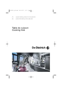
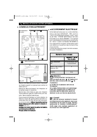
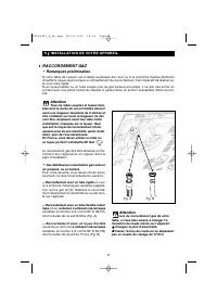
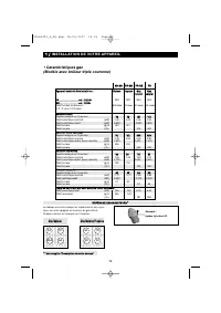
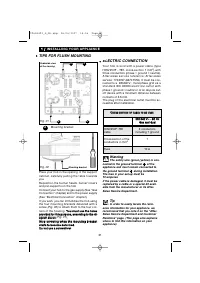
ELECTRIC CONNECTION
Yo u r h o b i s s o l d w i t h a p o w e r c a b l e ( t y p e
H05V2V2F - T90, cross-section 1 mm
2
) with
three conductors (phase + ground + neutral).
A f te r- s a l e s s e r v i c e r e f e r e n c e : A f te r- s a l e s
service: 77X3767 (6470.1516). It must be con-
nected to a 220-240 V~ monophase grid via a
s t a n d a r d I E C 6 0 0 8 3 e l e c t r i c a l o u t l et w i t h
phase + ground + neutral or or an all-pole cut-
off device with a minimum distance between
contacts of 3.5 mm.
The plug of the electrical outlet must be ac-
cessible after installation.
Warning
The safety wire (green/yellow) is con-
nected to the ground terminal
of the
appliance and must remain connected to
the ground terminal
during installation.
The fuse in your set-up must be
10 amperes
If the power cable is damaged, it must be
replaced by a cable or a special kit avail-
able from the manufacturer or its After-
Sales Service Department.
Tip
In order to easily locate the refer-
ence information for your appliance, we
recommend that you note it on the “After-
Sales Service Department and Customer
Relations” page. (This page also explains
where to find this information on your
appliance).
1
1 // INSTALLING YOUR APPLIANCE
A
A
A
A
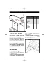
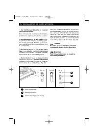
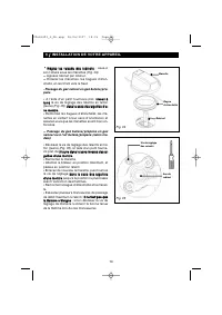
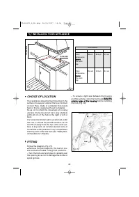
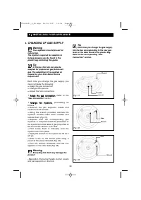
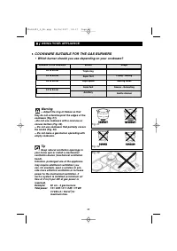
•
•
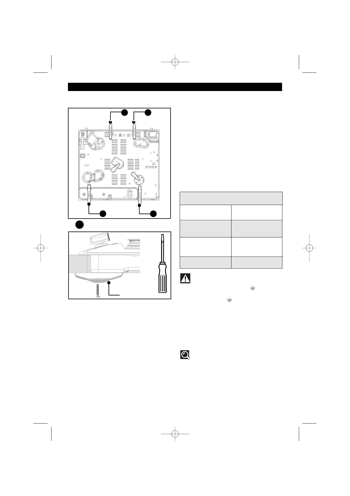
Place your hob in the opening of the support
cabinet, carefully pulling the table towards
you.
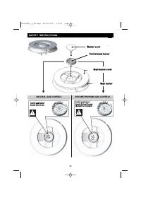
Reposition the burner heads, burner covers
and pan supports on the hob.
Connect your hob to the gas supply (See “Gas
Connection” chapter) and to the power supply
(See “Electrical Connection” chapter).
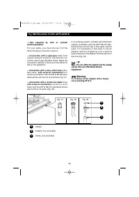
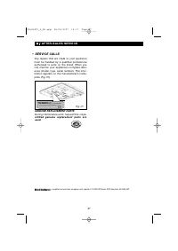
If you wish, you can immobilise the hob using
the four mounting brackets delivered with a
screw
(Fig. 02) to attach them to the four cor-
ners of the housing. Y
Yo
ou
u m
mu
us
stt u
us
se
e tth
he
e h
ho
olle
es
s
p
prro
ov
viid
de
ed
d ffo
orr tth
hiis
s p
pu
urrp
po
os
se
e,, a
ac
cc
co
orrd
diin
ng
g tto
o tth
he
e d
dii--
a
ag
grra
am
m a
ab
bo
ov
ve
e
(Fig. 01)..
S
Stto
op
p s
sc
crre
ew
wiin
ng
g w
wh
he
en
n tth
he
e m
mo
ou
un
nttiin
ng
g b
brra
ac
ck
ke
ett
s
stta
arrtts
s tto
o b
be
ec
co
om
me
e d
de
effo
orrm
me
ed
d..
D
Do
o n
no
ott u
us
se
e a
a s
sc
crre
ew
wd
drriiv
ve
err.
C
C
R
RO
OS
SS
S
--
S
SE
EC
CT
TIIO
ON
N O
OF
F C
CA
AB
BL
LE
E T
TO
O B
BE
E U
US
SE
ED
D
Fig. 01
Fig. 02
Mounting bracket
Underside view
of the housing
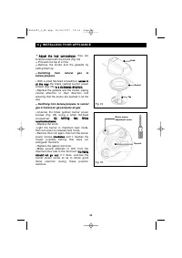
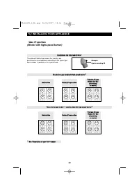
•
•
TIPS FOR FLUSH MOUNTING
Mounting bracket
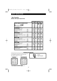
A
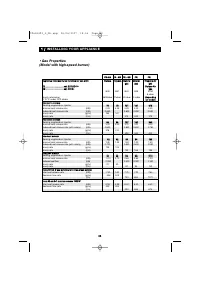
H05V2V2F -T90
cable
Cross-section of the
conductors in mm
2
Fuse
2
22
20
0--2
24
40
0 V
V~
~ -- 5
50
0 H
Hz
z
G
Ga
as
s a
an
nd
d d
du
ua
all
3 conductors
including 1 ground
1
10 A
99643492_A_ML.qxp 08/06/2007 14:16 Page 31
Характеристики

Остались вопросы?Не нашли свой ответ в руководстве или возникли другие проблемы? Задайте свой вопрос в форме ниже с подробным описанием вашей ситуации, чтобы другие люди и специалисты смогли дать на него ответ. Если вы знаете как решить проблему другого человека, пожалуйста, подскажите ему :)


