Сварочное оборудование Telwin BIMAX 132 TURBO - инструкция пользователя по применению, эксплуатации и установке на русском языке. Мы надеемся, она поможет вам решить возникшие у вас вопросы при эксплуатации техники.
Если остались вопросы, задайте их в комментариях после инструкции.
"Загружаем инструкцию", означает, что нужно подождать пока файл загрузится и можно будет его читать онлайн. Некоторые инструкции очень большие и время их появления зависит от вашей скорости интернета.

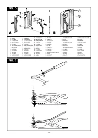
Connecting the welding current return cable
This is connected to the piece being welded or to the metal bench
WARNING:
supporting it, as close as possible to the join being made.
- In some models the wireguide tip is normally live; take care to
prevent unwanted strikes.
Connecting the torch (only for versions with EURO connector)
- The indicator light comes on when there is overheating and cuts off
Engage the torch with its dedicated connector by tightening the
the power supply; it will reset automatically within a few minutes,
locking ring manually as far down as it will go. Prepare the wire for
after cooling down.
loading the first time by dismantling the nozzle and the contact tube to
ease its exit.
7. MAINTENANCE
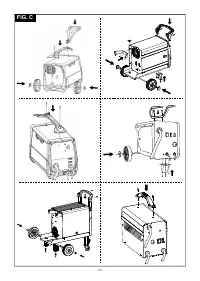
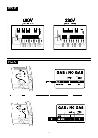
Changing the polarity
(only for GAS-NO GAS versions)
WARNING! BEFORE CARRYING OUT MAINTENANCE
Fig. G
- Open the reel compartment door.
OPERATIONS MAKE SURE THE WELDING MACHINE IS
- MIG/MAG welding (gas):
SWITCHED OFF AND DISCONNECTED FROM THE MAIN POWER
- Connect the torch cable from the wire feeder to the red terminal
SUPPLY.
(+).
- Connect the clamp return cable to the black terminal (-).
ROUTINE MAINTENANCE:
ROUTINE MAINTENANCE OPERATIONS CAN BE CARRIED OUT
- FLUX welding (no gas):
BY THE OPERATOR.
- Connect the torch cable from the wire feeder to the black terminal
(-).
Torch
- Connect the clamp return cable to the red terminal (+).
- Do not put the torch or its cable on hot pieces; this would cause the
- Close the reel compartment door.
insulating materials to melt, making the torch unusable after a very
short time;
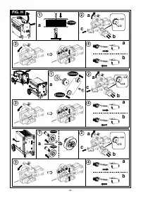
LOADING THE WIRE REEL (Fig. H)
- Make regular checks on the gas pipe and connector seals;
- Every time the wire reel is changed, blow out the wire-guide hose
WARNING! BEFORE STARTING THE OPERATIONS TO LOAD
using dry compressed air (max. 5 bar) to make sure it is not
damaged;
THE WIRE MAKE SURE THE WELDING MACHINE IS SWITCHED
- Before every use, check the wear and correct assembly of the parts
OFF AND DISCONNECTED FROM THE MAIN POWER SUPPLY
at the end of the torch: nozzle, contact tip, gas diffuser.
OUTLET.
Wire feeder
MAKE SURE THAT THE WIRE FEEDER ROLLERS, THE WIRE
- Make frequent checks on the state of wear of the wire feeder
GUIDE HOSE AND THE CONTACT TIP OF THE TORCH MATCH
rollers, regularly remove the metal dust deposited in the feeder
THE DIAMETER AND TYPE OF WIRE TO BE USED AND MAKE
area (rollers and wire-guide infeed and outfeed).
SURE THAT THESE ARE FITTED CORRECTLY. WHEN
INSERTING AND THREADING THE WIRE DO NOT WEAR
EXTRAORDINARY MAINTENANCE:
PROTECTIVE GLOVES.
EXTRAORDINARY MAINTENANCE OPERATIONS SHOULD BE
- Open the reel compartment door.
CARRIED OUT ONLY AND EXCLUSIVELY BY SKILLED OR
- Position the wire reel on the spindle, holding the end of the wire
AUTHORISED ELECTRICAL-MECHANICAL TECHNICIANS.
upwards; make sure the tab for pulling the spindle is correctly
seated in its hole
(1a)
.
- Release the pressure counter-roller(s) and move them away from
WARNING! BEFORE REMOVING THE WELDING MACHINE
the lower roller(s)
(2a)
;
PANELS AND WORKING INSIDE THE MACHINE MAKE SURE THE
- Make sure that the towing roller(s) is suited to the wire used
(2b)
.
WELDING MACHINE IS SWITCHED OFF AND DISCONNECTED
- Free the end of the wire and remove the distorted end with a clean
FROM THE MAIN POWER SUPPLY OUTLET.
cut and no burr; turn the reel anti-clockwise and thread the end of
If checks are made inside the welding machine while it is live, this
the wire into the wire-guide infeed, pushing it 50-100mm into the
may cause serious electric shock due to direct contact with live
wire guide of the torch fitting
(2c)
.
parts and/or injury due to direct contact with moving parts.
- Re-position the counter-roller(s), adjusting the pressure to an
- Inspect the welding machine regularly, with a frequency
intermediate value, and make sure that the wire is correctly
depending on use and the dustiness of the environment, and
positioned in the groove of the lower roller(s)
(3)
remove the dust deposited on the transformer, reactance and
- Use the adjustment screw located at the centre of the spindle to
rectifier using a jet of dry compressed air (max. 10 bar).
apply a slight braking pressure on the spindle itself
(1b)
.
- Do not direct the jet of compressed air on the electronic boards;
- Remove the nozzle and contact tip
(4a)
.
these can be cleaned with a very soft brush or suitable solvents.
- At the same time make sure the electrical connections are tight
- Insert the welding machine plug in the power supply outlet, switch
and check the wiring for damage to the insulation.
on the welding machine, press the torch button and wait for the
- At the end of these operations re-assemble the panels of the
end of the wire to pass through the whole of the wire guide hose
welding machine and screw the fastening screws right down.
and protrude by 10-15 cm from the front part of the torch, release
- Never, ever carry out welding operations while the welding
the button.
machine is open.
WARNING! During these operations the wire is live and
_______________(I)______________
subject to mechanical stress; therefore if adequate precautions
are not taken the wire could cause hazardous electric shock,
injury and striking of electric arcs:
MANUALE ISTRUZIONE
- Do not direct the mouthpiece of the torch towards parts of the body.
- Keep the torch away from the gas bottle.
- Re-fit the contact tip and the nozzle onto the torch
(4b)
.
- Check that wire feed is regular; set the roller and spindle braking
pressure to the minimum possible values making sure that the wire
ATTENZIONE:
does not slide in the groove and when feed is halted the loops of
P R I M A D I U T I L I Z Z A R E L A S A L D AT R I C E L E G G E R E
wire are not loosened by excessive reel inertia.
ATTENTAMENTE IL MANUALE DI ISTRUZIONE.
- Cut the end of the wire so that 10-15 mm protrude from the nozzle.
- Close the reel compartment door.
SALDATRICI A FILO CONTINUO PER LA SALDATURA AD ARCO
MIG/MAG E FLUX PREVISTE PER USO INDUSTRIALE E
6. WELDING: DESCRIPTION OF THE PROCEDURE
PROFESSIONALE.
-
Connect the return cable to the piece to be welded.
Nota: Nel testo che segue verrà impiegato il termine “saldatrice”.
-
Check the polarity (only for FLUX versions).
-
If solid wire is used, open and adjust the flow of shielding gas by
1. SICUREZZA GENERALE PER LA SALDATURA AD ARCO
means of the pressure reducer.
L'operatore deve essere sufficientemente edotto sull'uso sicuro
NOTE:
remember to shut the shielding gas off when you finish
della saldatrice ed informato sui rischi connessi ai procedimenti
work.
per saldatura ad arco, alle relative misure di protezione ed alle
-
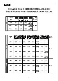
Switch the welder on and set the welding current by means of the
procedure di emergenza.
switches or rotary switch (if any).
( F a r e r i f e r i m e n t o a n c h e a l l a n o r m a " E N 6 0 9 7 4 - 9 :
Fig. I
Apparecchiature per saldatura ad arco. Parte 9: Installazione ed
- To start welding press the torch button.
uso").
-
To adjust the welding parameters adjust the wire feed rate (where
provided) using the appropriate knob until even welding is
obtained
(Fig.B-3).
- Evitare i contatti diretti con il circuito di saldatura; la tensione
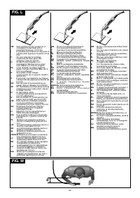
SPOT WELDING FUNCTION
(where provided)
a vuoto fornita dal generatore può essere pericolosa in talune
Fig. L
circostanze.
- To change the welding time operate the adjustment knob
(Fig.B-5).
- La connessione dei cavi di saldatura, le operazioni di verifica e
di riparazione devono essere eseguite a saldatrice spenta e
- 6 -


