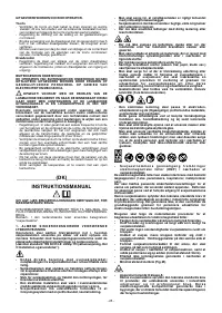
Сварочное оборудование Telwin BIMAX 132 TURBO - инструкция пользователя по применению, эксплуатации и установке на русском языке. Мы надеемся, она поможет вам решить возникшие у вас вопросы при эксплуатации техники.
Если остались вопросы, задайте их в комментариях после инструкции.
"Загружаем инструкцию", означает, что нужно подождать пока файл загрузится и можно будет его читать онлайн. Некоторые инструкции очень большие и время их появления зависит от вашей скорости интернета.

them;
THE POWER SUPPLY OUTLET.
- Lubricating the gears.
THE ELECTRICAL CONNECTIONS MUST BE MADE ONLY AND
SHOULD BE CARRIED OUT WITH THE WELDING MACHINE
EXCLUSIVELY BY AUTHORISED OR QUALIFIED PERSONNEL.
SWITCHED OFF AND DISCONNECTED FROM THE POWER
SUPPLY OUTLET.
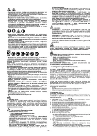
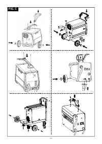
PREPARATION
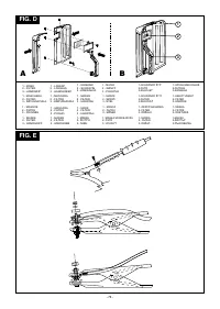
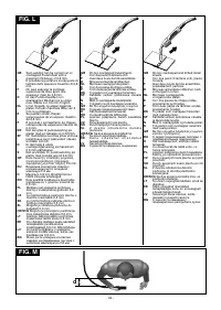
Fig. C
Unpack the welding machine, assemble the separate parts contained
- Never lift the welding machine .
in the package.
2. INTRODUCTION AND GENERAL DESCRIPTION
Assembling the protective mask
This welding machine is a power source used for arc welding and has
been designed specifically for MAG welding of carbon steel and low-
Fig. D
alloy steel with either CO or Argon/CO mixture shielding gas using
2
2
solid or cored (tubular) electrode wires. They are also suitable for MIG
Assembling the return cable-clamp
welding of stainless steel using Argon gas + 1-2% oxygen and of
Fig. E
aluminium with Argon gas using electrode wires with a composition
suited to the piece to be welded
(only models in Fig. B
1
).
HOW TO LIFT THE WELDING MACHINE
None of the welding machines described in this manual is equipped
It is also possible to use cored wires in applications without protective
with a lifting device.
gas by adapting the polarity of the torch to the wire manufacturer's
recommendations
(Model in Fig. B
2
uses only flux core wire).
SITE
Locate the welding machine in an area where openings for cooling air
STANDARD ACCESSORIES:
are not obstructed (forced circulation with fan), leave at least 250mm
- torch;
free space around the welding machine; check that conductive dusts,
- return cable complete with earth clamp;
corrosive vapours, humidity etc., will not enter welding machine.
- wheels kit (in models on wheels).
WARNING! Position the welding machine on a flat surface
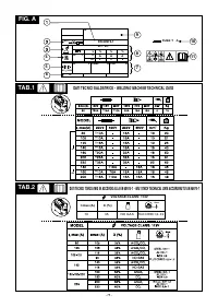
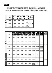
3. TECHNICAL DATA
with sufficient carrying capacity for its weight, to prevent it from
DATA PLATE
tipping or moving hazardously.
The most important data regarding use and performance of the
welding machine are summarised on the rating plate and have the
CONNECTION OF PLUG AND SOCKET (only applicable to
following meaning:
models supplied without plug):
connect a normalised plug
(2P + T
Fig. A
for 1ph, 3P + T for 3ph)
having sufficient capacity- to the power cable
1-
EUROPEAN standard of reference, for safety and construction of
and prepare a mains outlet fitted with fuses or an automatic circuit-
arc welding machines.
breaker; the special earth terminal should be connected to the earth
2-
Symbol for internal structure of the welding machine.
conductor (yellow-green) of the power supply line. Table 1
(TAB.1)
3-
Symbol for welding procedure provided.
shows the recommended delayed fuse sizes in amps, chosen
4-
Symbol
S
: indicates that welding operations may be carried out in
according to the max. nominal current supplied by the welding
environments with heightened risk of electric shock (e.g. very
machine, and the nominal voltage of the main power supply.
close to large metallic volumes).
5-
Symbol for power supply line:
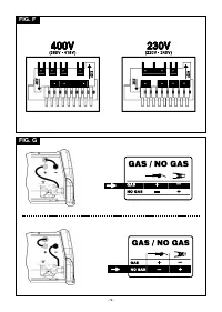
- To carry out voltage change operations(only the 3-phase version),
1~: single phase alternating voltage;
take off the panel to gain access to the inside of the machine, and
3~: 3-phase alternating voltage.
prepare the voltage change terminal board so that the connection
6-
Protection rating of the covering.
indicated on the special indicator plate corresponds to the available
7-
Technical specifications for power supply line:
power supply voltage.
- U :
Alternating voltage and power supply frequency of welding
1
Fig. F
machine (allowed limit ±10%).
Reassemble the panel carefully using the appropriate screws.
- I
:
Maximum current absorbed by the line.
1 max
Warning!
- I :
: effective current supplied.
1eff
In the factory the machine is set at the highest voltage of the
8-
Performance of the welding circuit:
available range, e.g.
- U :
maximum no-load voltage (open welding circuit).
0
U 400V
Ü
Voltage setting at the factory.
1
- I /U :
current and corresponding normalised voltage that the
2
2
welding machine can supply during welding.
CONNECTION TO THE MAIN POWER SUPPLY
- X :
Duty cycle: indicates the time for which the welding machine
- Before making any electrical connection, make sure the rating data
can supply the corresponding current (same column). It is
of the welding machine correspond to the mains voltage and
expressed as %, based on a 10 min. cycle (e.g. 60% = 6 minutes
frequency available at the place of installation.
working, 4 minutes pause, and so on)
.
- The welding machine should only be connected to a power supply
If the usage factors (on the plate, referring to a 40°C
system with the neutral conductor connected to earth.
environment) are exceeded, the thermal safeguard will trigger
- To comply with the requirements of the EN 61000-3-11 (Flicker)
(the welding machine will remain in standby until its temperature
standard we recommend connecting the welding machine to
returns within the allowed limits).
interface points of the power supply that have an impedance of less
- A/V-A/V:
shows the range of adjustment for the welding current
than Zmax =0.1 ohm.
(minimum maximum) at the corresponding arc voltage.
- the welding machine falls within the requisites of IEC/EN 61000-3-
9-
Manufacturer's serial number for welding machine identification
12 standard.
(indispensable for technical assistance, requesting spare parts,
discovering product origin).
WARNING!
10-
:
Size of delayed action fuses to be used to protect the
Failure to observe the above rules will make the (Class 1) safety
power line.
system installed by the manufacturer ineffective with
11-
Symbols referring to safety regulations, whose meaning is given in
consequent serious risks to persons (e.g. electric shock) and
chapter 1 “General safety considerations for arc welding”.
objects (e.g. fire).
Note: The data plate shown above is an example to give the meaning
CONNECTION OF THE WELDING CABLES
of the symbols and numbers; the exact values of technical data for the
welding machine in your possession must be checked directly on the
data plate of the welding machine itself.
WARNING!
BEFORE
MAKING
THE
FOLLOWING
CONNECTIONS MAKE SURE THE WELDING MACHINE IS
OTHER TECHNICAL DATA
SWITCHED OFF AND DISCONNECTED FROM THE POWER
SUPPLY OUTLET.
- WELDING MACHINE:
see table 1 (TAB.1)
Table 1
(TAB. 1)
gives the recommended values for the welding cables
- TORCH:
see table 2 (TAB.2)
2
(in mm ) depending on the maximum current supplied by the welding
machine.
The welding machine weight is shown in table 1
(TAB. 1).
Connection to the gas bottle (if used)
- Gas bottle can be loaded on welding machine bottle support
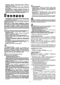
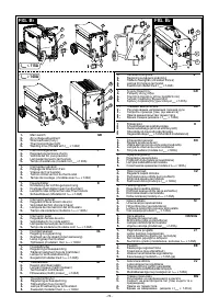
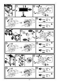
4. DESCRIPTION OF THE WELDING MACHINE
platform: max 20 kg.
CONTROL, ADJUSTMENT AND CONNECTION DEVICES
- Screw the pressure reducing valve(*) onto the gas bottle valve,
Fig. B
1
, B
2
inserting the appropriate adapter supplied as an accessory, for
when the gas used is Argon or an Argon /CO mixture.
2
5. INSTALLATION
- Connect the gas inlet pipe to the pressure-reducing valve and
tighten the band supplied.
WARNING!
- Loosen the adjustment ring nut on the pressure-reducing valve
before opening the bottle valve.
C A R RY O U T A L L I N S TA L L AT I O N O P E R AT I O N S A N D
(*) Accessory to be purchased separately if not supplied with the
ELECTRICAL CONNECTIONS WITH THE WELDING MACHINE
product.
COMPLETELY SWITCHED OFF AND DISCONNECTED FROM
- 5 -


