Памяти и накопители Seagate (ST16000NM002G) - инструкция пользователя по применению, эксплуатации и установке на русском языке. Мы надеемся, она поможет вам решить возникшие у вас вопросы при эксплуатации техники.
Если остались вопросы, задайте их в комментариях после инструкции.
"Загружаем инструкцию", означает, что нужно подождать пока файл загрузится и можно будет его читать онлайн. Некоторые инструкции очень большие и время их появления зависит от вашей скорости интернета.


Seagate Exos X16 SAS Product Manual, Rev. K
60
www.seagate.com
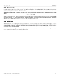
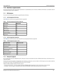
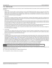
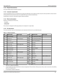
Interface requirements
11.5.2 Differential signals
The drive SAS differential signals comply with the intra-enclosure (internal connector) requirements of the SAS standard.
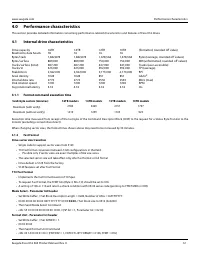
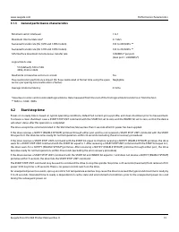
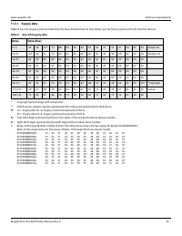
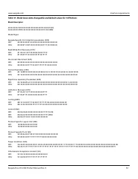
Table 18 defines the general interface characteristics.
11.6
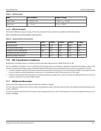
SAS-3 Specification Compliance
Seagate SAS-3 compatible drives are compliant with the latest SAS-3 Specification ( T10/BSR INCITS 519 rev. 06).
The main difference from SAS-2 is the Tx and Rx training that allows the host and drive to adjust the amplitude and emphasis values to the
channel. The receiver still employs Decision Feedback Equalizer (DFE) and Feed Forward Equalizer (FFE) circuitry to accomplish this training.
1.
A Decision Feedback Equalizer (DFE) which utilizes the standard SAS-2 training pattern transmitted during the SNW-3 training gap. The DFE
circuit can derive an optimal equalization characteristic to compensate for many of the receive losses in the system.
2.
A Feed Forward Equalizer (FFE) optimized to provide balanced receive margins over a range of channels bounded by the best and worst case
channels as defined by the relevant ANSI standard.
11.7
Additional information
Please contact the Seagate representative for SAS electrical details, if required.
For more information about the Phy, Link, Transport, and Applications layers of the SAS interface, refer to the Seagate SAS Interface Manual, part
number 100293071.
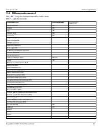
For more information about the SCSI commands used by Seagate SAS drives, refer to the Seagate SCSI Commanrds Reference Manual, part
number 100293068.
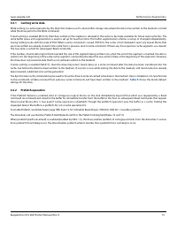
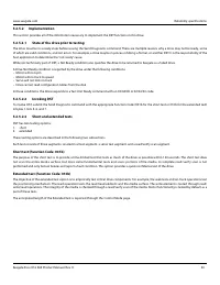
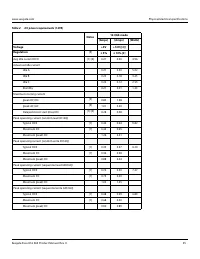
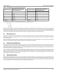
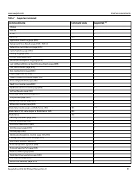
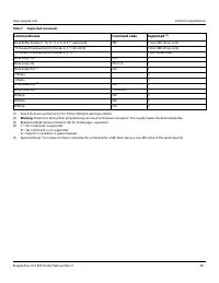
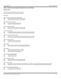
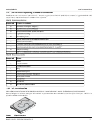
Table 17 LED drive signal
State
Test condition
Output voltage
LED off, high
0 V ≤VOH ≤ 3.6 V
-100 μA < I
OH
< 100 μA
LED on, low
I
OL
= 15 mA
0 ≤ V
OL
≤ 0.225 V
Table 18 General interface characteristics
Characteristic
Units
1.5Gb/s
3.0Gb/s
6.0Gb/s
12 Gbps
Bit rate (nominal)
Mbaud
1,500
3,000
6,000
12000
Unit interval (UI) (nominal)
ps
666.6
333.3
166.6
83.3
Impedance (nominal, differential)
ohm
100
100
100
100
Transmitter transients, maximum
V
± 1.2
± 1.2
± 1.2
± 1.2
Receiver transients, maximum
V
± 1.2
± 1.2
± 1.2
± 1.2
Характеристики

Остались вопросы?Не нашли свой ответ в руководстве или возникли другие проблемы? Задайте свой вопрос в форме ниже с подробным описанием вашей ситуации, чтобы другие люди и специалисты смогли дать на него ответ. Если вы знаете как решить проблему другого человека, пожалуйста, подскажите ему :)

