Памяти и накопители Seagate (ST16000NM002G) - инструкция пользователя по применению, эксплуатации и установке на русском языке. Мы надеемся, она поможет вам решить возникшие у вас вопросы при эксплуатации техники.
Если остались вопросы, задайте их в комментариях после инструкции.
"Загружаем инструкцию", означает, что нужно подождать пока файл загрузится и можно будет его читать онлайн. Некоторые инструкции очень большие и время их появления зависит от вашей скорости интернета.


Seagate Exos X16 SAS Product Manual, Rev. K
59
www.seagate.com
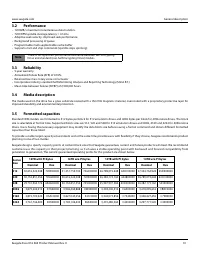
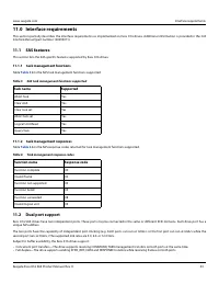
Interface requirements
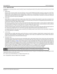
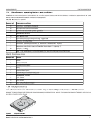
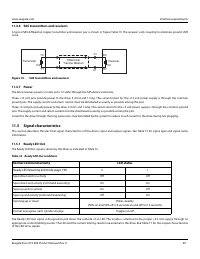
11.4.6 SAS transmitters and receivers
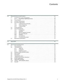
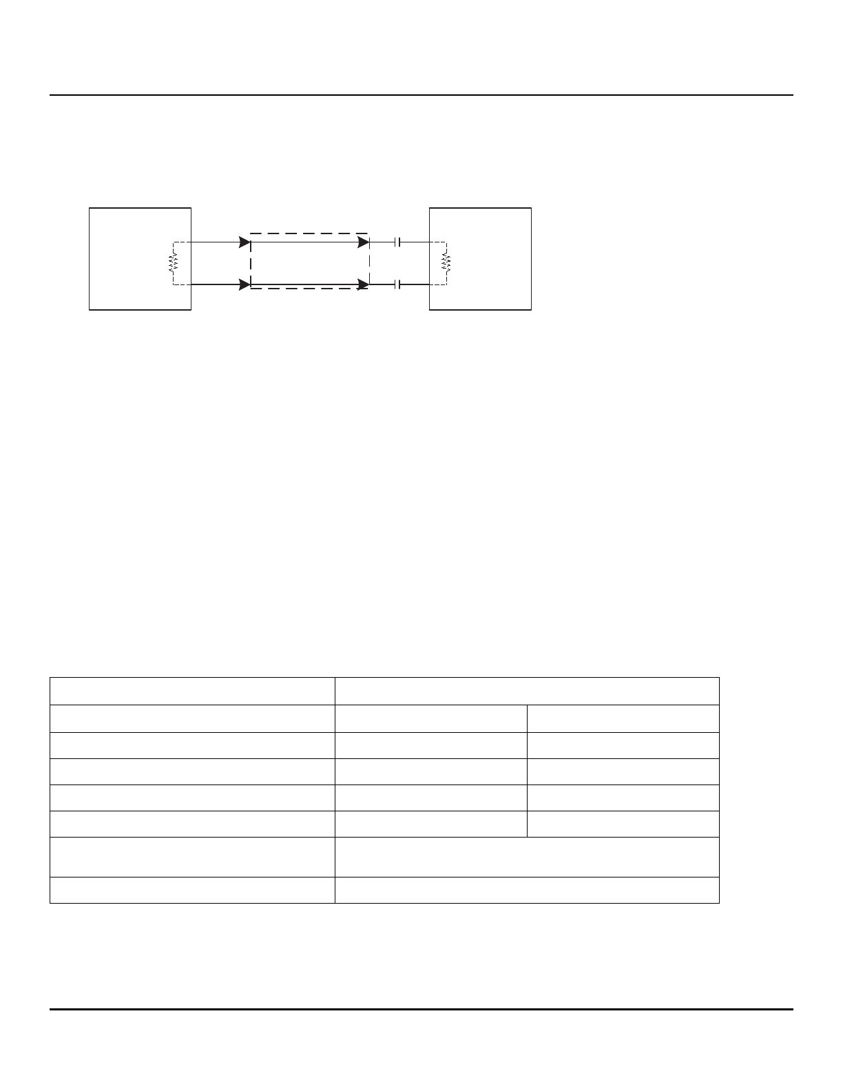
A typical SAS differential copper transmitter and receiver pair is shown in Figure Table 10. The receiver is AC coupling to eliminate ground shift
noise.
Figure 10.
SAS transmitters and receivers
11.4.7 Power
The drive receives power (+5 volts and +12 volts) through the SAS device connector.
Three +12 volt pins provide power to the drive, 2 short and 1 long. The current return for the +12 volt power supply is through the common
ground pins. The supply current and return current must be distributed as evenly as possible among the pins.
Three +5 volt pins provide power to the drive, 2 short and 1 long. The current return for the +5 volt power supply is through the common ground
pins. The supply current and return current must be distributed as evenly as possible among the pins.
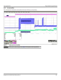
Current to the drive through the long power pins may be limited by the system to reduce inrush current to the drive during hot plugging.
11.5
Signal characteristics
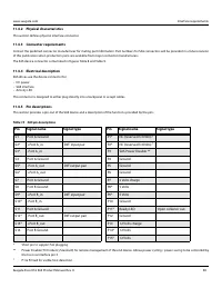
This section describes the electrical signal characteristics of the drive’s input and output signals. See Table 15 for signal type and signal name
information.
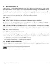
11.5.1 Ready LED Out
The Ready LED Out signal is driven by the drive as indicated in Table 16.
The Ready LED Out signal is designed to pull down the cathode of an LED. The anode is attached to the proper +3.3 volt supply through an
appropriate current limiting resistor. The LED and the current limiting resistor are external to the drive. See Table 17 for the output characteristics
of the LED drive signals.
Table 16 Ready LED Out conditions
Normal command activity
LED status
Ready LED Meaning bit mode page 19h
0
1
Spun down and no activity
Off
Off
Spun down and activity (command executing)
On
On
Spun up and no activity
On
Off
Spun up and activity (command executing)
Off
On
Spinning up or down
Blinks steadily
(50% on and 50% off, 0.5 seconds on and off for 0.5 seconds)
Format in progress, each cylinder change
Toggles on/off
Receiver
Differential
Transfer Medium
.01
.01
100
100
Transmitter
RX
RY
TX
TY
Характеристики

Остались вопросы?Не нашли свой ответ в руководстве или возникли другие проблемы? Задайте свой вопрос в форме ниже с подробным описанием вашей ситуации, чтобы другие люди и специалисты смогли дать на него ответ. Если вы знаете как решить проблему другого человека, пожалуйста, подскажите ему :)

