Памяти и накопители Micron 2933 - инструкция пользователя по применению, эксплуатации и установке на русском языке. Мы надеемся, она поможет вам решить возникшие у вас вопросы при эксплуатации техники.
Если остались вопросы, задайте их в комментариях после инструкции.
"Загружаем инструкцию", означает, что нужно подождать пока файл загрузится и можно будет его читать онлайн. Некоторые инструкции очень большие и время их появления зависит от вашей скорости интернета.
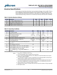
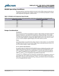

DRAM Operating Conditions
Recommended AC operating conditions are given in the DDR4 component data sheets.
Component specifications are available at micron.com. Module speed grades correlate
with component speed grades, as shown below.
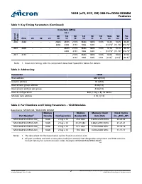
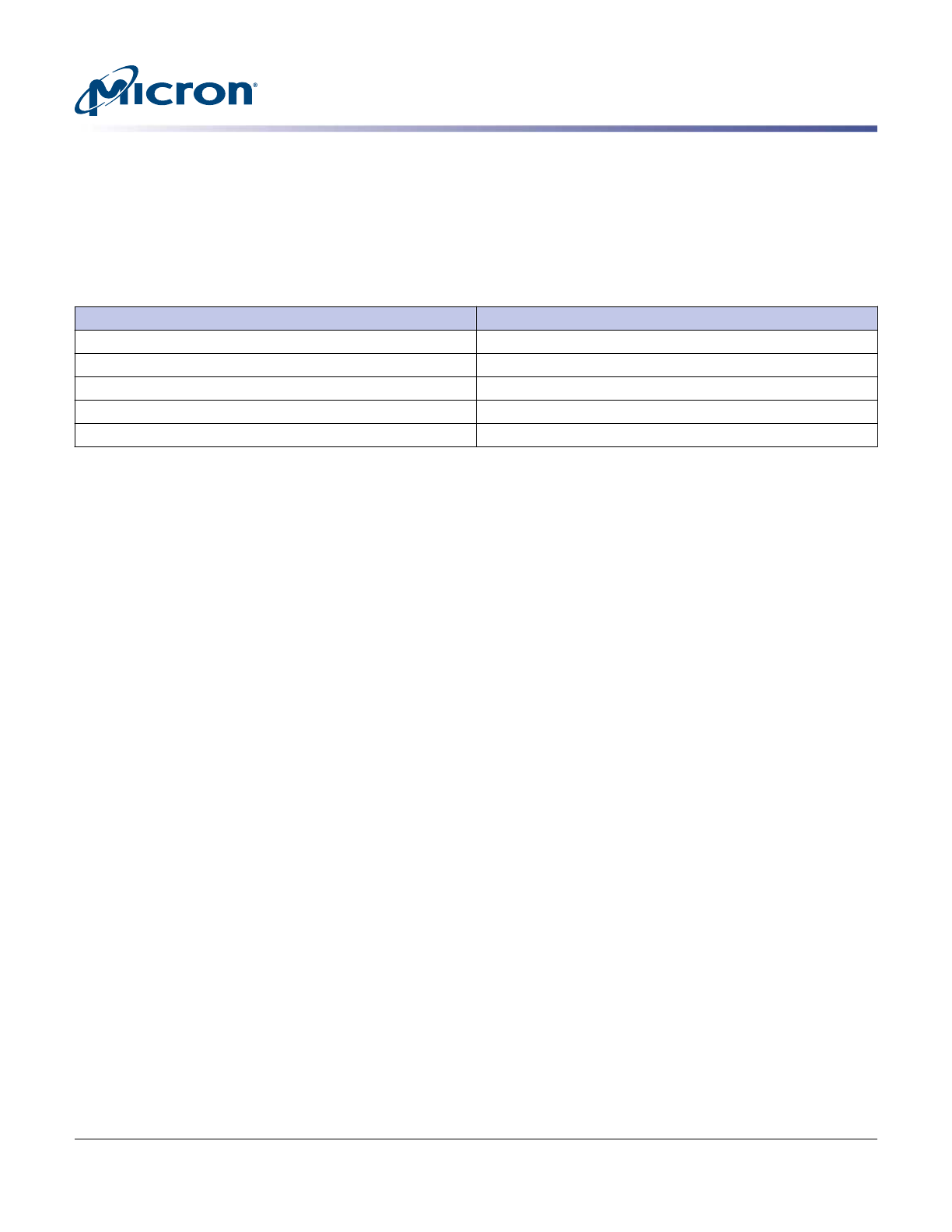
Table 12: Module and Component Speed Grades
DDR4 components may exceed the listed module speed grades; module may not be available in all listed speed grades
Module Speed Grade
Component Speed Grade
-3G2
-062E
-2G9
-068
-2G6
-075
-2G3
-083
-2G1
-093E
Design Considerations
Simulations
Micron memory modules are designed to optimize signal integrity through carefully de-
signed terminations, controlled board impedances, routing topologies, trace length
matching, and decoupling. However, good signal integrity starts at the system level. Mi-
cron encourages designers to simulate the signal characteristics of the system's memo-
ry bus to ensure adequate signal integrity of the entire memory system.
Power
Operating voltages are specified at the edge connector of the module, not at the DRAM.
Designers must account for any system voltage drops at anticipated power levels to en-
sure the required supply voltage is maintained.
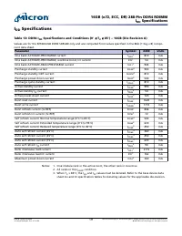
I
DD
, I
PP
, and I
DDQ
Specifications
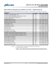
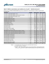
I
DD
and I
PP
values are only for the DDR4 SDRAM and are calculated from values in the
supporting component data sheet. I
PP
and I
DDQ
currents are not included in I
DD
cur-
rents. I
DD
and I
DDQ
currents are not included in I
PP
currents. Micron does not specify
I
DDQ
currents. In DRAM module application, I
DDQ
cannot be measured separately be-
cause V
DD
and V
DDQ
use a merged power layer in the module PCB.
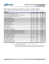
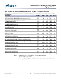
Certain I
DD
/I
PP
conditions must be derated for optional modes of operation, such as CA
parity, DBI, write CRC, additive latency, geardown, CAL, 2X and 4X REF, and DLL disa-
bled. Refer to the base device data sheet I
DD
and I
PP
specification tables for derating val-
ues for the applicable die revision.
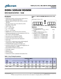
16GB (x72, ECC, DR) 288-Pin DDR4 RDIMM
DRAM Operating Conditions
CCMTD-1725822587-9899
asf18c2gx72pdz.pdf - Rev. H 7/19 EN
18
Micron Technology, Inc. reserves the right to change products or specifications without notice.
© 2015 Micron Technology, Inc. All rights reserved.
Характеристики

Остались вопросы?Не нашли свой ответ в руководстве или возникли другие проблемы? Задайте свой вопрос в форме ниже с подробным описанием вашей ситуации, чтобы другие люди и специалисты смогли дать на него ответ. Если вы знаете как решить проблему другого человека, пожалуйста, подскажите ему :)


