Материнские платы GIGABYTE GA 73PVM S2H rev 1 0 - инструкция пользователя по применению, эксплуатации и установке на русском языке. Мы надеемся, она поможет вам решить возникшие у вас вопросы при эксплуатации техники.
Если остались вопросы, задайте их в комментариях после инструкции.
"Загружаем инструкцию", означает, что нужно подождать пока файл загрузится и можно будет его читать онлайн. Некоторые инструкции очень большие и время их появления зависит от вашей скорости интернета.
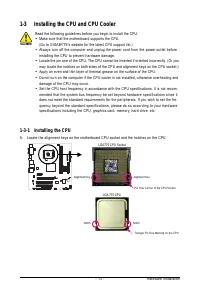
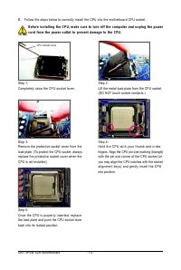
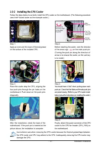
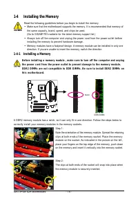
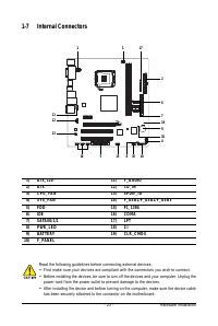
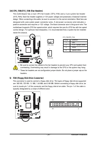
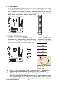
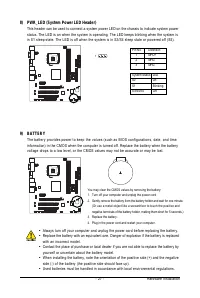
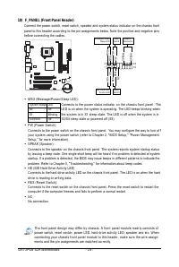
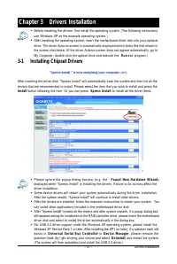
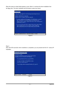
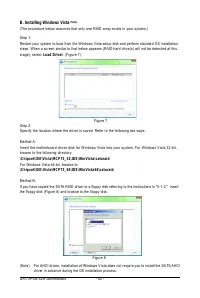
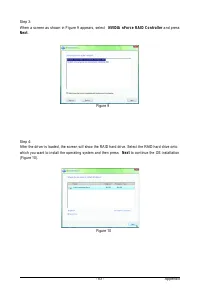


Hardware Installation
- 29 -
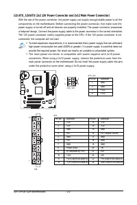
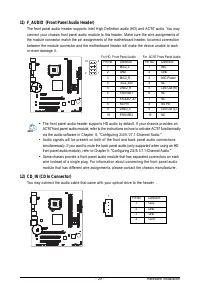
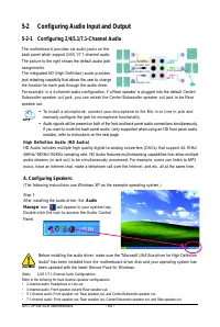
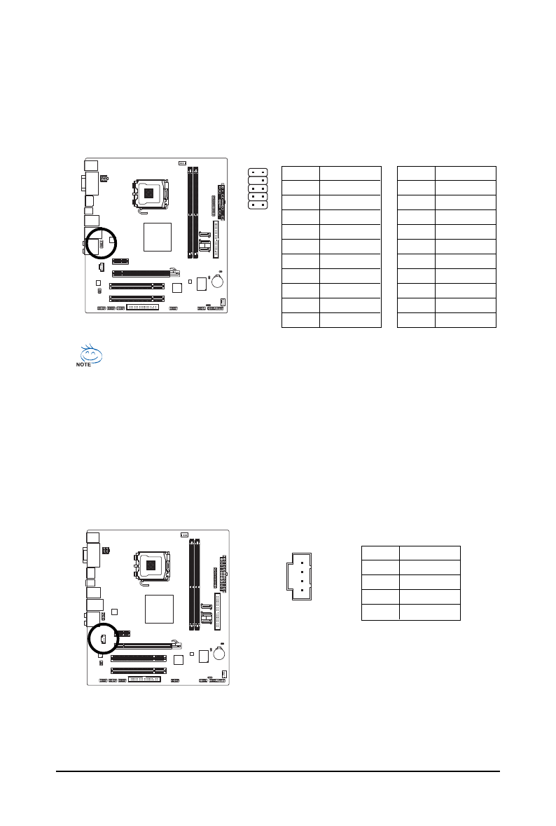
11) F_AUDIO (Front Panel Audio Header)
The front panel audio header supports Intel H igh D efinition audio (HD) and AC'97 audio. You may
connect your chassis front panel audio module to this header. Make sure the wire assignments of
the module connector match the pin assignments of the motherboard header. Incorrect connection
between the module connector and the motherboard header will make the device unable to work
or even damage it.
For AC'97 Front Panel Audio:
Pin No.
Definition
1
MIC2_L
2
GND
3
MIC2_R
4
-ACZ_DET
5
LINE2_R
6
FSENSE1
7
FAUDIO_JD
8
No Pin
9
LINE2_L
10
FSENSE2
For HD Front Panel Audio:
•
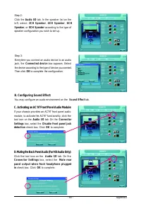
The front panel audio header supports HD audio by default. If your chassis provides an
AC'97 front panel audio module, refer to the instructions on how to activate AC'97 functioninality
via the audio software in Chapter 5, "Configuring 2/4/5.1/7.1-Channel Audio."
•
Audio signals will be present on both of the front and back panel audio connections
simultaneously. If you want to mute the back panel audio (only supported when using an HD
front panel audio module), refer to Chapter 5, "Configuring 2/4/5.1/7.1-Channel Audio."
•
Some chassis provide a front panel audio module that has separated connectors on each
wire instead of a single plug. For information about connecting the front panel audio
module that has different wire assignments, please contact the chassis manufacturer.
Pin No.
Definition
1
MIC
2
GND
3
MIC Power
4
NC
5
Line Out (R)
6
NC
7
NC
8
No Pin
9
Line Out (L)
10
NC
12) CD_IN (CD In Connector)
You may connect the audio cable that came with your optical drive to the header .
Pin No.
Definition
1
CD-L
2
GND
3
GND
4
CD-R
1
2
9
1 0
1


