
Электрорубанки Bosch 0.601.5A0.300 - инструкция пользователя по применению, эксплуатации и установке на русском языке. Мы надеемся, она поможет вам решить возникшие у вас вопросы при эксплуатации техники.
Если остались вопросы, задайте их в комментариях после инструкции.
"Загружаем инструкцию", означает, что нужно подождать пока файл загрузится и можно будет его читать онлайн. Некоторые инструкции очень большие и время их появления зависит от вашей скорости интернета.


16
| English
1 609 92A 0KP | (13.5.14)
Bosch Power Tools
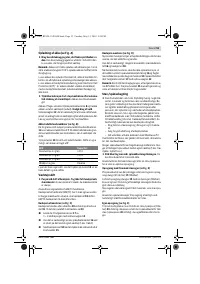
Do not reach into the saw dust ejector with your hands.
They could be injured by rotating parts.
To ensure optimum extraction of dust/chips, always work
with external dust extraction or a chip/dust bag.
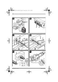
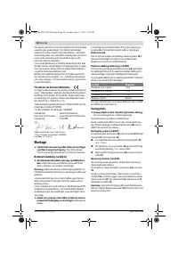
External Dust Extraction (see figure E)
An extraction hose (Ø 35 mm)
19
(accessory), can be at-
tached on either side of the chip ejector.
Connect the vacuum hose
19
to a vacuum cleaner (accesso-
ry). An overview for connecting to various vacuum cleaners
can be found at the end of this manual.
The vacuum cleaner must be suitable for the material being
worked.
When vacuuming dry dust that is especially detrimental to
health or carcinogenic, use a special vacuum cleaner.
Integrated Dust Extraction (see figure E)
A chip/dust bag (accessory)
20
can be used for smaller jobs.
Insert the sleeve of the chip/dust bag firmly into the chip ejec-
tor
1
. Empty the chip/dust bag
20
at regulary intervals to
maintain optimum dust collection.
Choice of Chip Ejector Side
With the selector lever
4
, the chip ejector
1
can be switched
to right or left. Always press the selector lever
4
until it engag-
es in the end position. The selected ejection direction is indi-
cated by an arrow symbol on the selector lever
4
.
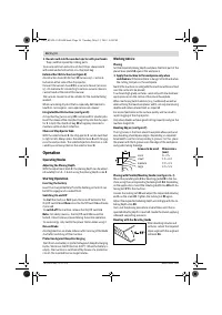
Operation
Operating Modes
Adjusting the Planing Depth
With the adjustment knob
2
, the planing depth can be adjust-
ed variably from 0 – 1.6 mm using the planing depth scale
3
.
Starting Operation
Inserting the battery
Insert the charged battery
7
into the battery port until it can
be felt to engage and is seated flush.
Switching On and Off
To
start
the machine,
first
push the lock-off button for the
On/Off switch
5
and
then
press the On/Off switch
6
and keep
it pressed.
To
switch off
the machine, release the On/Off switch
6
.
Note:
For safety reasons, the On/Off switch
6
cannot be
locked; it must remain pressed during the entire operation.
To save energy, only switch the power tool on when using it.
Run-on Brake
An integrated run-on brake reduces after-running of the blade
shaft after switching off the machine.
Protection Against Deep Discharging
The lithium-ion battery is protected against deep discharging
by the “Electronic Cell Protection (ECP)”. When the battery is
empty, the machine is switched off by means of a protective
circuit: The inserted tool no longer rotates.
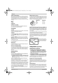
Working Advice
Planing
Set the required planing depth and place the front part of the
planer base plate
10
against the workpiece.
Apply the machine to the workpiece only when
switched on.
Otherwise there is danger of kickback when
the cutting tool jams in the workpiece.
Switch the machine on and guide the machine with even feed
over the surface to be planed.
To achieve high-grade surfaces, work only with low feed and
apply pressure on the centre of the planer base plate.
When machining hard materials (e. g. hardwood) as well as
when utilising the maximum planer width, set only low planing
depths and reduce planer feed, as required.
Excessive feed reduces the surface quality and can lead to
rapid clogging of the chip ejector.
Only sharp blades achieve good cutting capacity and give the
machine longer life.
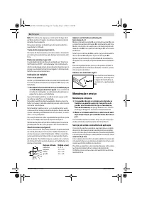
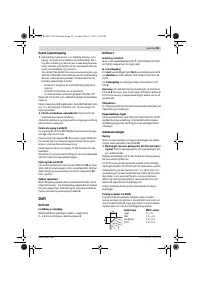
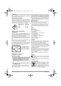
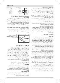
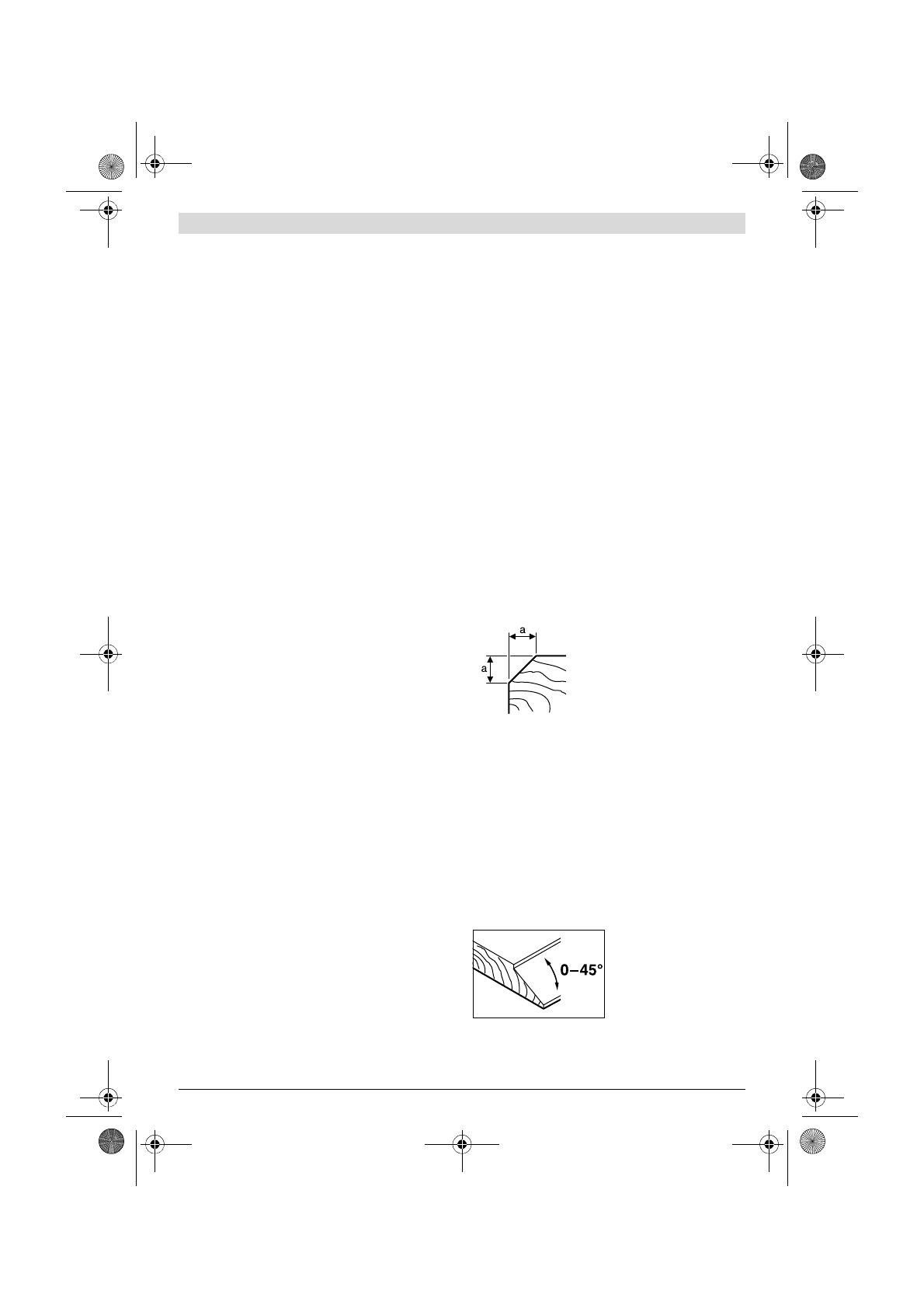
Beveling Edges (see figure F)
The V-grooves in the front planer base plate allow quick and
easy beveling of workpiece edges. Depending on required
bevel width, use the corresponding V-groove. For this, place
the planer with the V-groove onto the edge of the workpiece
and guide it along the edge.
Planing with Parallel/Beveling Guide (see figure G – I)
Mount the parallel guide
21
or beveling guide
25
to the ma-
chine using the corresponding fastening bolt
24
. Depending
on the application, mount the rebating depth stop
28
with fas-
tening bolt
27
to the machine.
Loosen the locking nut
23
and adjust the requested rebating
width on the scale
22
. Tighten the locking nut
23
again.
Adjust the requested rebating depth accordingly with the re-
bating depth stop
28
.
Carry out the planing procedure several times until the re-
quested rebating depth is reached. Guide the planer applying
sideward supporting pressure.
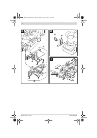
Beveling with the Beveling Guide
When beveling rebates and
surfaces, adjust the required
slope angle with the angle ad-
justment
26
.
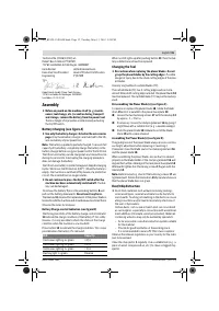
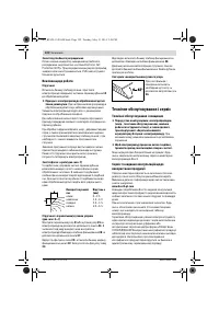
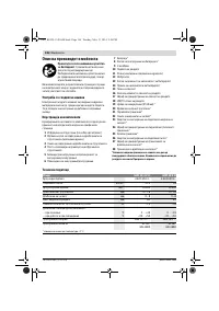
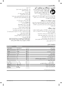
Groove to be used
Dimension a
(mm)
none
0 – 2.5
small
1.5 – 4.0
medium
2.0 – 4.5
large
3.0 – 5.5
OBJ_BUCH-1520-004.book Page 16 Tuesday, May 13, 2014 2:26 PM
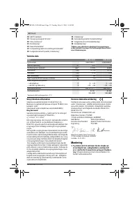
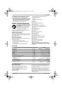
Характеристики

Остались вопросы?Не нашли свой ответ в руководстве или возникли другие проблемы? Задайте свой вопрос в форме ниже с подробным описанием вашей ситуации, чтобы другие люди и специалисты смогли дать на него ответ. Если вы знаете как решить проблему другого человека, пожалуйста, подскажите ему :)


