Электропилы Bosch GTS 10 J Professional - инструкция пользователя по применению, эксплуатации и установке на русском языке. Мы надеемся, она поможет вам решить возникшие у вас вопросы при эксплуатации техники.
Если остались вопросы, задайте их в комментариях после инструкции.
"Загружаем инструкцию", означает, что нужно подождать пока файл загрузится и можно будет его читать онлайн. Некоторые инструкции очень большие и время их появления зависит от вашей скорости интернета.


36
| English
1 619 929 J53 | (12.5.11)
Bosch Power Tools
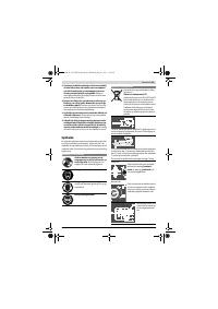
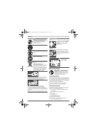
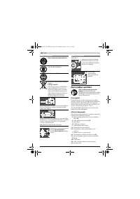
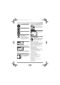
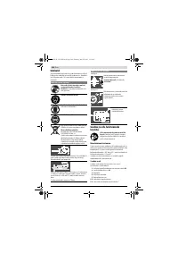
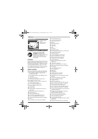
Checking:
The mark of lens
27
must be in a line with the 0 ° mark of scale
1
.
Adjusting:
– Loosen screw
62
using a Phillips screwdriver and align the
clearance indicator alongside the 0 ° mark.
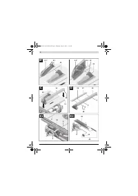
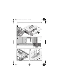
Adjusting the Level of the Insert Plate (see figure X)
Checking:
The front side of the insert plate
24
must be flush with or
somewhat lower than the saw table; the rear side must be
flush with or somewhat above the saw table.
Adjusting:
– Remove the insert plate
24
.
– Adjust the correct level of the four adjusting screws
63
with the Allen key
64
.
Adjusting the Tension Force of the Parallel Guide
The tensioning force of the parallel guide
10
can decrease af-
ter frequent usage.
– Tighten the adjustment screw
70
until the parallel guide
can be firmly affixed on the saw table again.
Storage and Transport
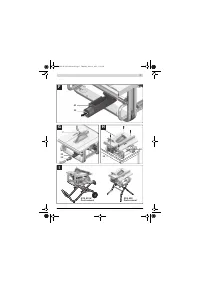
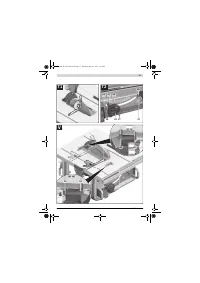
Storing Product Features (see figures Y1 – Y6)
For storage purposes, certain product features can be se-
curely fastened to the power tool.
– Loosen auxiliary parallel guide
37
from parallel guide
10
.
– Attach all loose tool parts to their storage locations on the
housing. (see Table)
Carrying the Power Tool
Before transporting the power tool, the following steps must
be carried out:
– Bring the machine into the transport position. (see “Trans-
port Position”, page 33)
– Remove all accessories that cannot be mounted firmly to
the power tool.
If possible, place unused saw blades in an enclosed con-
tainer for transport.
– Slide the saw-table extension
14
completely to the rear
and press tensioning lever
15
downward to lock it.
– Wind the mains cable around the cable holder
29
.
– For lifting or transport, use the recessed handles
4
or the
carrying handle
13
.
f
When transporting the power tool, use only the trans-
port devices and never use the protective devices.
f
The power tool should always be carried by two per-
sons in order to avoid back injuries.
Maintenance and Service
Maintenance and Cleaning
f
Before any work on the machine itself, pull the mains
plug.
If the machine should fail despite the care taken in manufac-
turing and testing procedures, repair should be carried out by
an after-sales service centre for Bosch power tools.
In all correspondence and spare parts order, please always in-
clude the 10-digit article number given on the type plate of
the machine.
Cleaning
– For safe and proper working, always keep the power tool
and its ventilation slots clean.
– Remove dust and chips after each working procedure by
blowing out with compressed air or with a brush.
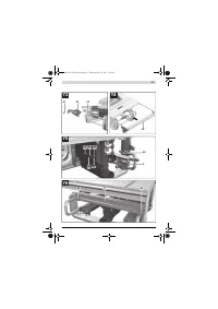
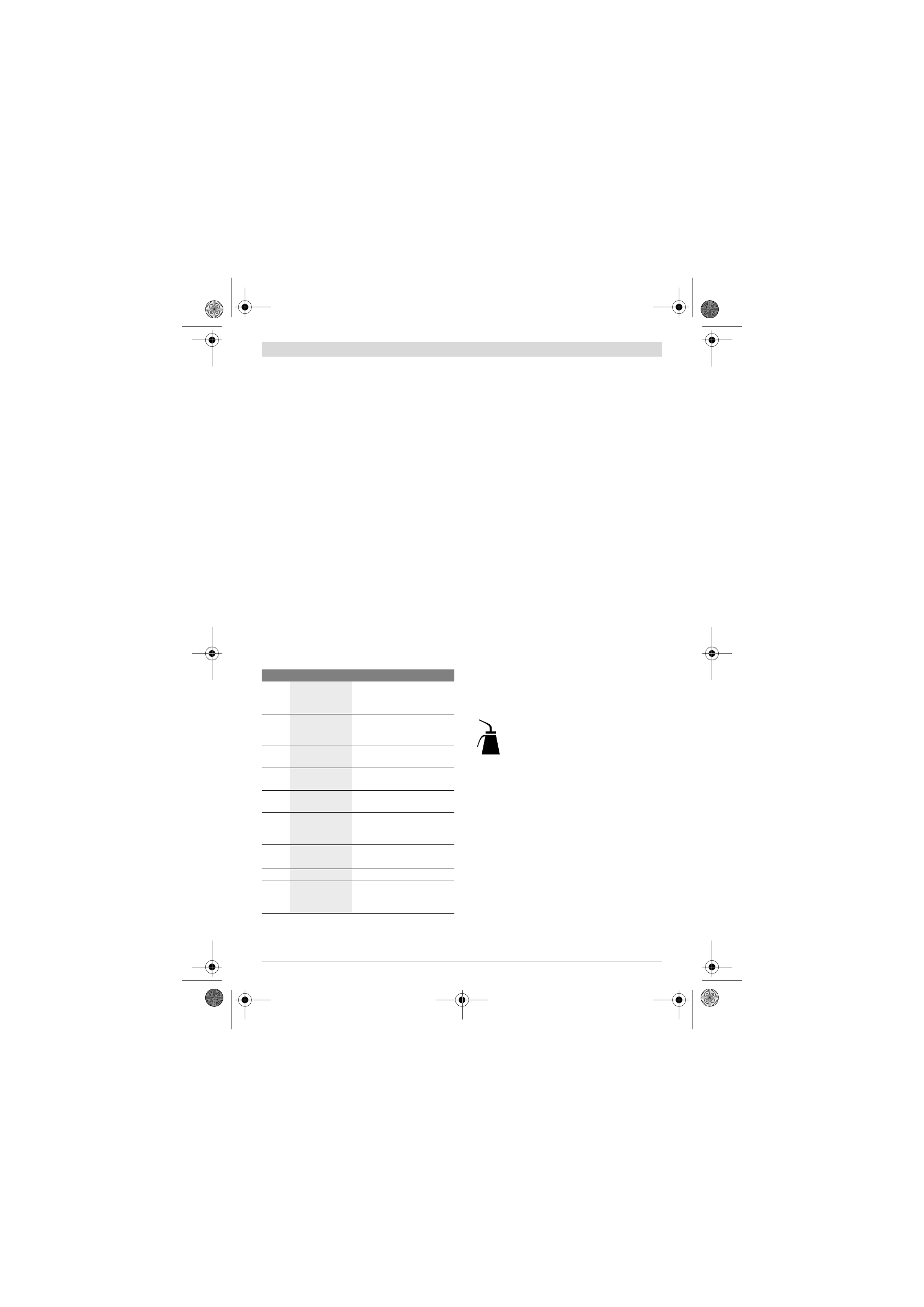
Power Tool Lubrication
Lubricants:
SAE 10/SAE 20 engine oil
– If required, lubricate the power tool at the indicated loca-
tions. (see figure Z)
An authorized Bosch after-sales service agent will carry out
this work quickly and reliably.
Observe all applicable environmental regulations when
disposing of old grease and solvents.
Measures for Noise Reduction
Measures on behalf of the manufacturer:
– Soft starting
– Delivery of the machine with a saw blade developed partic-
ularly for noise reduction
Measures on behalf of the user:
– Low-vibration assembly on a firm working surface
– Use of saw blades with noise-reducing functions
– Regular cleaning of saw blade and power tool
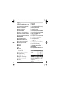
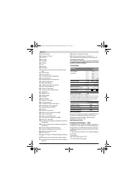
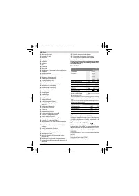
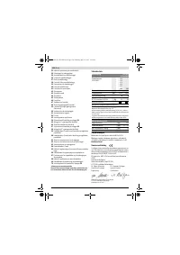
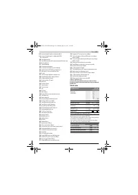
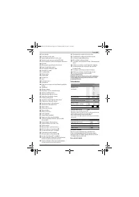
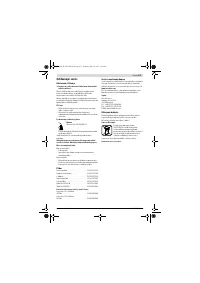
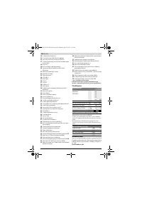
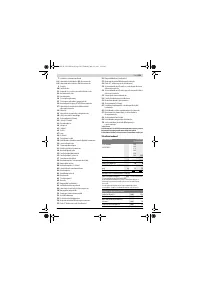
Figure Product Feature Storage Location
Y1
Blade guard
6.x
Insert into the recess of fixture
33
and tighten with clamping
lever
8.1
or clamping screw
8.2
Y2
“Auxiliary parallel
guide” fastening
kit
38
Clip into the holders
65
Y2
Extraction adapter
32
Insert into retaining clamp
66
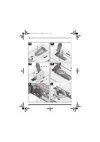
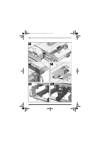
Y3
Ring spanner
22
Fasten in tool depot with
fastening nut
67
Y3
Push stick
23
Mount onto fastening nut
67
and fasten by turning
Y4
Parallel guide
10
Turn guide around and hang it
into the guide rails from below;
tighten clamping handle
35
Y5
Allen key
21
Allen key
64
Insert into holders
68
Y5
Angle stop
3
Insert into retaining clamp
69
Y6
Auxiliary parallel
guide
37
Insert into retaining brackets
30
(short side goes on top; long
side toward the rear)
OBJ_BUCH-1325-002.book Page 36 Thursday, May 12, 2011 1:51 PM


