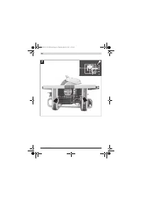
Электропилы Bosch GTS 10 J Professional - инструкция пользователя по применению, эксплуатации и установке на русском языке. Мы надеемся, она поможет вам решить возникшие у вас вопросы при эксплуатации техники.
Если остались вопросы, задайте их в комментариях после инструкции.
"Загружаем инструкцию", означает, что нужно подождать пока файл загрузится и можно будет его читать онлайн. Некоторые инструкции очень большие и время их появления зависит от вашей скорости интернета.


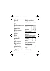


English |
35
Bosch Power Tools
1 619 929 J53 | (12.5.11)
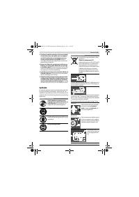
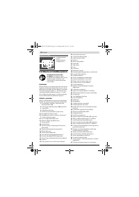
– Adjust the blade guard according to the workpiece height.
When sawing, the blade guard must always face lightly
against the workpiece.
– Switch on the machine.
– Saw through the workpiece applying uniform feed.
– Switch off the machine and wait until the saw blade has
come to a complete stop.
Sawing Bevel Angles
– Adjust the desired bevel angle. (see “Adjusting Bevel An-
gles”, page 33)
– Follow the worksteps in section “Sawing Straight Cuts” ac-
cordingly.
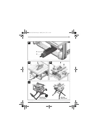
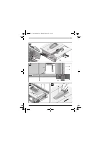
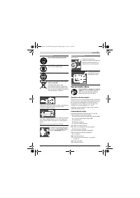
Sawing Mitre Angles (see figure S)
– Adjust the requested mitre angle (see “Adjusting Mitre An-
gles”, page 33)
– Place the workpiece against profile rail
28
.
The profile may not be on the cutting line. If so, loosen
knurled nut
53
and move the profile.
– Raise or lower the saw blade with the crank
19
so that the
upper saw teeth project approx. 5 mm above the work-
piece surface.
– Adjust the blade guard according to the workpiece height.
When sawing, the blade guard must always face lightly
against the workpiece.
– Switch on the machine.
– With one hand, press the workpiece against the profile rail
and with the other hand, slowly move the angle stop via
locking knob
49
toward the front in guide groove
5
.
– Switch off the machine and wait until the saw blade has
come to a complete stop.
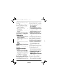
Checking and Adjusting the Basic Adjustment
To ensure precise cuts, the basic adjustment of the machine
must be checked and adjusted as necessary after intensive
use.
A certain level of experience and appropriate specialty tools
are required for this.
A Bosch after-sales service station will handle this mainte-
nance task quickly and reliably.
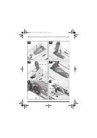
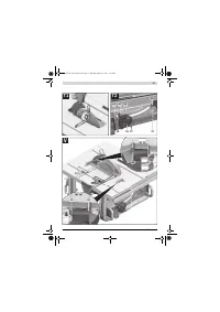
Setting the Stops for Standard 0 ° / 45 ° Bevel Angles
– Bring the power tool into the working position.
– Adjust to a 0 ° bevel angle.
– Tilt the protection guard
6.x
toward the rear to the stop.
Checking:
(see figure T1)
– Set an angle gauge to 90 ° and place it on the saw table
9
.
The leg of the angle gauge must be flush with the saw blade
26
over the complete length.
Adjusting:
(see figure T2)
– Loosen screw
54
.
The 0 ° stop
55
can now be moved.
– Loosen locking lever
17
.
– Move handwheel
18
toward the 0° stop until the leg of the
angle gauge is flush with the saw blade over the complete
length.
– Hold the handwheel in this position and tighten locking le-
ver
17
again.
– Tighten screw
54
again.
When the angle indicator
47
is not in line with the 0 ° mark of
scale
48
, loosen screw
56
with a commercially available Phil-
lips screwdriver and align the angle indicator alongside the 0 °
mark.
Repeat the above mentioned worksteps accordingly for the
45 ° bevel angle (loosening screw
57
; moving the 45° stop
58
). In this, the angle indicator
47
must not be misadjusted.
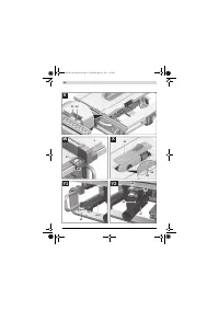
Parallelism of the Saw Blade to the Guide Grooves of the
Angle Stop (see figure U)
– Bring the power tool into the working position.
– Tilt the protection guard
6.x
toward the rear to the stop.
Checking:
– With a pencil, mark the first visible saw tooth on the left
side that projects above the insert plate.
– Set an angle gauge to 90 ° and place it on the edge of the
guide groove
5
.
– Move the leg of the angle gauge until it touches the marked
saw tooth, and read the clearance between saw blade and
guide groove.
– Turn the saw blade until the marked tooth projects above
the right side of the insert plate.
– Move the angle gauge alongside the guide groove to the
marked tooth.
– Measure the clearance between the saw blade and guide
groove again.
Both clearances measured must be identical.
Adjusting:
– Loosen Allen screws
59
at the front below the saw table
and Allen screws
60
at the rear below the saw table with
the supplied Allen key
21
.
– Carefully move the saw blade until it is parallel to guide
groove
5
.
– Retighten all screws
59
and
60
again.
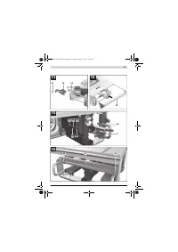
Adjusting the Saw Table’s Clearance Indicator
(see figure V)
– Position the parallel guide on the right side of the saw
blade.
Move the parallel guide until the mark in the lens
27
indi-
cates 26 cm on the bottom scale.
To lock the parallel guide, press clamping handle
35
down
again.
– Loosen tensioning lever
15
and pull the table extension out
to the stop.
Checking:
On the upper scale
1
, clearance indicator
51
must indicate
the identical value as the mark in lens
27
on the bottom scale
1
.
Adjusting:
– Loosen screw
61
with a Phillips screwdriver and align
clearance indicator
51
alongside the 26 cm mark of the up-
per scale
1
.
Adjusting the Lens of the Parallel Guide (see figure W)
– Bring the power tool into the working position.
– Tilt the protection guard
6.x
toward the rear to the stop.
– Move parallel guide
10
from the right until it touches the
saw blade.
OBJ_BUCH-1325-002.book Page 35 Thursday, May 12, 2011 1:51 PM


